Optical detection and ranging sensor system for sense and avoid, and related methods

a sensor system and optical detection technology, applied in the field of range detection and collision avoidance, can solve the problems of high false alarm rate, unwittingly highlighting, system affecting the operational mission of the uas, etc., and achieve the effect of reducing false alarm ra

Active Publication Date: 2013-03-19
LOCKHEED MARTIN CORP
View PDF12 Cites 22 Cited by
  • Summary
  • Abstract
  • Description
  • Claims
  • Application Information

AI Technical Summary

Benefits of technology

[0011]In view of the foregoing, various embodiments of the present invention advantageously provide apparatus, optical systems, program product, and methods for passively sensing and avoiding aerial targets. Various embodiments of the present invention advantageously provide apparatus, optical systems, program product, and methods for providing passive sensing and facilitating avoiding airborne obstacles can advantageously provide image acquisition using both narrow and wide fields of view at substantially the same time, which can allow an unmanned aerial system (UAS) or vehicle (UAV) to detect and avoid another airborne object having a 22.5 square meters optical cross-section and located within a field of regard of ±15 degrees Elevation and ±110 degrees Azimuth at a range of at least approximately 10 kilometers with a probability of detection of 90% or better at night and in bad weather. Advantageously, various embodiments of the apparatus, optical systems, program product, and methods can allow the UAS to respond so that collision is avoided by at least 500 ft.
[0013]The optical system can also include a second focal plane array positioned to generate image data according to the wide field of view, and a beam splitter, flip mirror, half silvered mirror, or other similar light divider or other form of channeler positioned to simultaneously or alternatingly provide the optical image of the aerial environment according to the wide field of view to the scan mirror assembly and to the second focal plane array. The optical system can also include a second spatial light modulator positioned in optical communication with the light channeler and the second focal plane array to adjust the relative aperture size of light directed to the second focal plane array to rapidly optimize blur differential between images and / or objects within an image to enhance determining atmospheric blur and range estimates, and to adjust the light intensity of light directed to the second focal plane array responsive to environmental lighting conditions of the light received from the light channeler to thereby maintain the light intensity of the light directed to the second focal plane array below a maximum intensity level. The apparatus can also include a sensor control and image processor configured to provide control signals to the various controllable components of the optical system and to receive image data from the focal plane arrays.
[0016]The method can also, or alternatively, include determining an approximate range of each of the plurality of airborne objects within the wide field of view of the optical system, determining one of the plurality of airborne objects located within the wide field of view of the first portion of the optical system to have a highest priority, positioning components of the second portion of the optical system so that the highest priority airborne object is within the narrow field of view of the second portion of the optical system, determining a first, a second, and a third approximate range to the highest priority airborne object, determining the approximate direction and velocity of the high-priority airborne object responsive to the determined first and second approximate ranges, and projecting an anticipated location of the highest priority airborne object during a next range determination responsive to the determined third approximate range. The method can also include panning first and second scan mirrors to substantially position a center of the narrow field of view at approximately the anticipated location of the highest priority airborne object during the next range determination responsive to the projecting to enhance determining range, direction, and velocity of the highest priority airborne object, and determining an enhanced value for the range, direction, and velocity of the high-priority airborne object responsive to the panning.
[0019]Various embodiments of the present invention include a beam splitter to allow the apparatus to simultaneously analyze both wide and narrow fields at the cost of some light. Alternative embodiments of the present invention utilize a mirror which deflects the focused rays of light through a different optical path after the primary lens of the sensor system to provide interleaved operation with little loss of light. Various embodiments of the present invention utilize a piezo-electric device or other mechanism to move an optical detector array along the optical axis to produced focused and defocused images, quickly and accurately and in such a manner that the distance is know or is easily determined.
[0020]Various embodiments of the present invention advantageously combine use of lowlight electro-optical (TV) camera / shortwave IR sensors and mid-band IR sensors / long wave IR sensors to provide daytime, nighttime, bad weather capabilities. Various features can include dual baud detectors, spatial light modulators to provide adaptive aperture and light control, spatial light modulators to reduce the effective image overlap, multiple sensors using multiple fields of view—wide field of view processing followed by narrow field of view operation, with common optics using two scanning mirrors, a field of regard of 30 degrees vertically and 44 degrees horizontally for each of, e.g., five sensors to create a ±15 degrees elevation and ±110 degrees azimuth, and track filtering to eliminate false alarms. According to various embodiments of the present invention, the optical system employs a wide field of view portion having a high false alarm rate followed by narrow field of view with multiple looks to confirm true targets with good range data and to eliminate false alarms.
[0021]Various embodiments of the present invention provide enhanced range accuracy, passive image acquisition, subpixel object detection, multiple fields of view, a wide field of regard coverage, simultaneous multiple fields of view with narrow field of view operation over the entire wide field of view without use of gimbals or motion of vehicle, and / or a sensor control and image processor which employs an algorithm capable of range measurements with a single sensor and fixed focus setting which can detect objects smaller than a pixel without need for two cameras.

Problems solved by technology

Such maneuvers, however, disrupt the operational mission of the UAS and can unwittingly highlight the location of the UAS in a hostile environment.
Also, besides long convergence times, such systems suffer from high false alarm rates.
This method typically suffers from high cost due to double optics, sensor alignment and vibration problems, along with high computational costs, large baseline separation requirements, and dual tracking problems.
The large field of regard needed to meet the sense and avoid design space can also present a major problem as multiple sets of data may be required.
Accordingly, such methodology can be relatively slow, both in acquiring the imaged data, and in resolving the data.
Such method can also require a great deal of system resources.
Each failed to perform to the desired standards even minimally.
Recognized by the inventors, however, is that such configuration would, in many instances, be inadequate for a less maneuverable aircraft such as a UAS that can only pull less than 2 Gs.
Further, recognized by the inventors is that existing algorithms which have been published fail to provide for determining range at long ranges (e.g. 10 kilometers) due to atmospheric effects, and thus, would not be capable of performing to the prescribed standards unless possibly the air is perfectly still and atmospheric loss of signal is taken into account.
The optical system could include a beam splitter or other light divider, but at the cost of some light.

Method used


Image

  • Optical detection and ranging sensor system for sense and avoid, and related methods
  • Optical detection and ranging sensor system for sense and avoid, and related methods
  • Optical detection and ranging sensor system for sense and avoid, and related methods

Examples


Embodiment Construction

[0049]The present invention will now be described more fully hereinafter with reference to the accompanying drawings, which illustrate embodiments of the invention. This invention may, however, be embodied in many different forms and should not be construed as limited to the illustrated embodiments set forth herein. Rather, these embodiments are provided so that this disclosure will be thorough and complete, and will fully convey the scope of the invention to those skilled in the art. Like numbers refer to like elements throughout. Prime notation, if used, indicates similar elements in alternative embodiments.

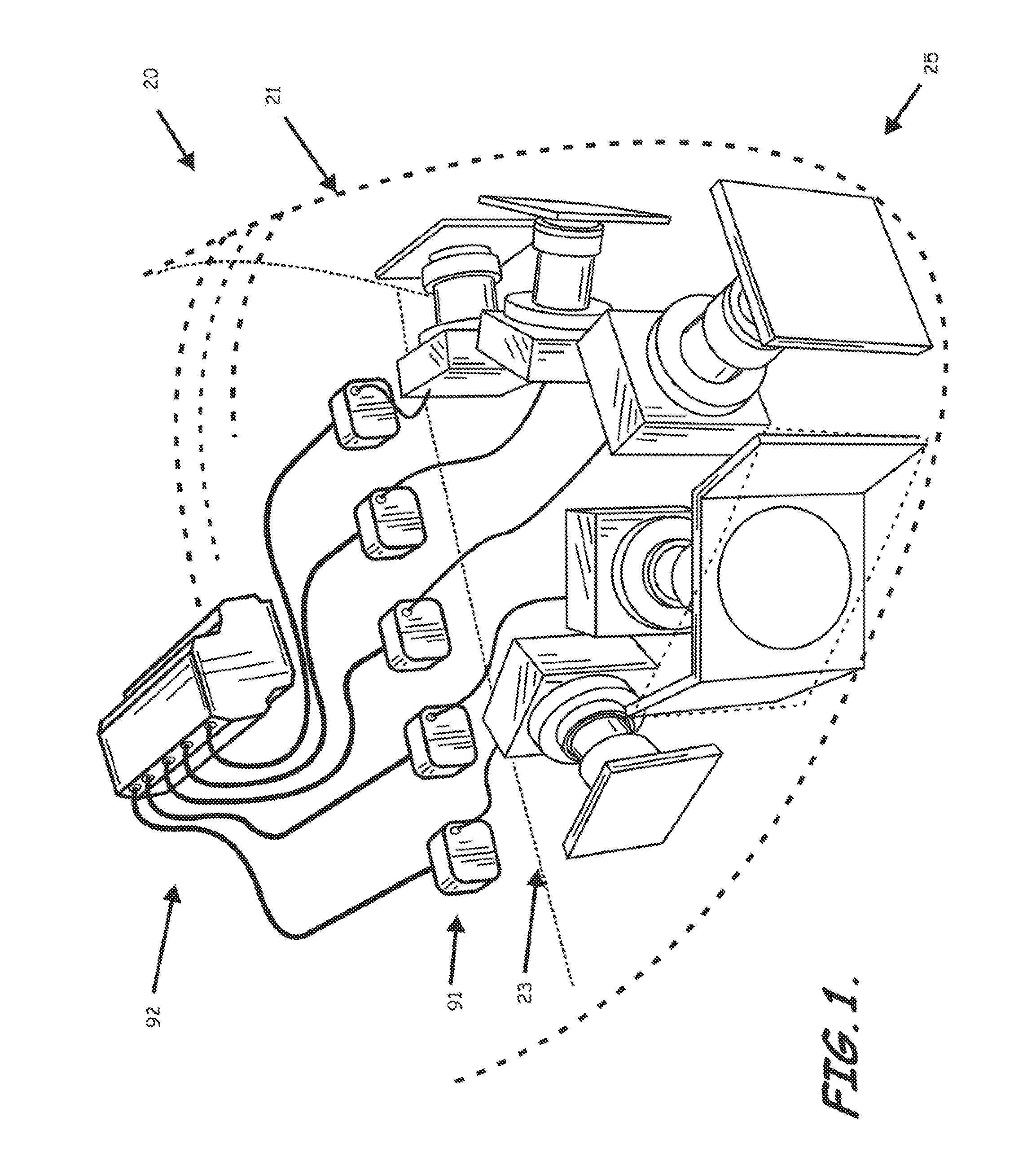
[0050]As perhaps best shown in FIG. 1, an apparatus 20 carried by an unmanned vehicle as known to those skilled in the art, such as, for example, aerial vehicle 21, to provide passive sensing and facilitate avoiding, e.g., airborne obstacles, also as known to those skilled in the art, is provided. The apparatus 20 can include at least one, but typically five, optical systems 23...


PUM


Abstract

An apparatus carried by an unmanned vehicle to provide passive sensing and facilitate avoiding airborne aerial obstacles is provided. The apparatus can include at least one, but typically multiple optical systems installed, for example, in the nose of the aerial vehicle to passively sense and determine a range, direction, and velocity of the airborne obstacles to allow the aerial vehicle to avoid the airborne obstacles. The typical optical system includes at least one focal plane array or other imaging device configured to receive a wide field of view and at least one focal plane array or other imaging device configured to receive a steerable narrow field of view within the wide field of view to allow concentrated determination of the range, direction, and / or velocity of obstacles detected by the wide field of view imaging devices.

Description

BACKGROUND OF THE INVENTION[0001]1. Field of the Invention[0002]The present invention relates generally to range detection and collision avoidance. More specifically, the present invention relates to apparatus, optical systems, program product, and methods for passively sensing and avoiding aerial targets.[0003]2. Description of the Related Art[0004]The American Society for Testing and Materials (ASTM) International established Committee F-38 on unmanned aircraft systems (UASs) or unmanned aerial vehicles (UAVs) to identify design and performance standards for airborne sense-and-avoid systems. The committee has recently issued standards that require a UAS / UAV to be able to detect and avoid another airborne object within a field of regard of ±15 degrees Elevation and ±110 degrees Azimuth and to be able to respond so that collision is avoided by at least 500 ft. The 500 ft safety bubble is derived from the commonly accepted definition of what constitutes a near mid-air collision. The ...

Claims


Application Information

Patent Timeline
Patent Type & Authority Patents(United States)
IPC IPC(8): H04N5/33H04N7/18
CPCG01C3/08G02B26/101G05D1/101H04N5/33G05D1/106
Inventor WOOD, RHANDE P.JONES, MICHAEL I.
Owner LOCKHEED MARTIN CORP
Why Eureka
Try Eureka