[0011]In view of the foregoing, various embodiments of the present invention advantageously provide apparatus, optical systems, program product, and methods for passively sensing and avoiding aerial targets. Various embodiments of the present invention advantageously provide apparatus, optical systems, program product, and methods for providing
passive sensing and facilitating avoiding airborne obstacles can advantageously provide
image acquisition using both narrow and wide fields of view at substantially the same time, which can allow an unmanned aerial system (UAS) or vehicle (UAV) to
detect and avoid another airborne object having a 22.5 square meters optical cross-section and located within a field of regard of ±15 degrees Elevation and ±110 degrees
Azimuth at a range of at least approximately 10 kilometers with a probability of detection of 90% or better at night and in
bad weather. Advantageously, various embodiments of the apparatus, optical systems, program product, and methods can allow the UAS to respond so that collision is avoided by at least 500 ft.
[0013]The optical system can also include a second focal plane array positioned to generate image data according to the wide
field of view, and a
beam splitter, flip mirror, half silvered mirror, or other similar light divider or other form of channeler positioned to simultaneously or alternatingly provide the
optical image of the aerial environment according to the wide
field of view to the scan mirror
assembly and to the second focal plane array. The optical system can also include a second
spatial light modulator positioned in
optical communication with the light channeler and the second focal plane array to adjust the relative aperture size of light directed to the second focal plane array to rapidly optimize blur differential between images and / or objects within an image to enhance determining atmospheric blur and range estimates, and to adjust the
light intensity of light directed to the second focal plane array responsive to
environmental lighting conditions of the light received from the light channeler to thereby maintain the
light intensity of the light directed to the second focal plane array below a
maximum intensity level. The apparatus can also include a sensor control and
image processor configured to provide control signals to the various controllable components of the optical system and to receive image data from the
focal plane arrays.
[0016]The method can also, or alternatively, include determining an approximate range of each of the plurality of airborne objects within the wide field of view of the optical system, determining one of the plurality of airborne objects located within the wide field of view of the first portion of the optical system to have a highest priority, positioning components of the second portion of the optical system so that the highest priority airborne object is within the narrow field of view of the second portion of the optical system, determining a first, a second, and a third approximate range to the highest priority airborne object, determining the approximate direction and velocity of the high-priority airborne object responsive to the determined first and second approximate ranges, and projecting an anticipated location of the highest priority airborne object during a next range determination responsive to the determined third approximate range. The method can also include panning first and second scan mirrors to substantially position a center of the narrow field of view at approximately the anticipated location of the highest priority airborne object during the next range determination responsive to the projecting to enhance determining range, direction, and velocity of the highest priority airborne object, and determining an enhanced value for the range, direction, and velocity of the high-priority airborne object responsive to the panning
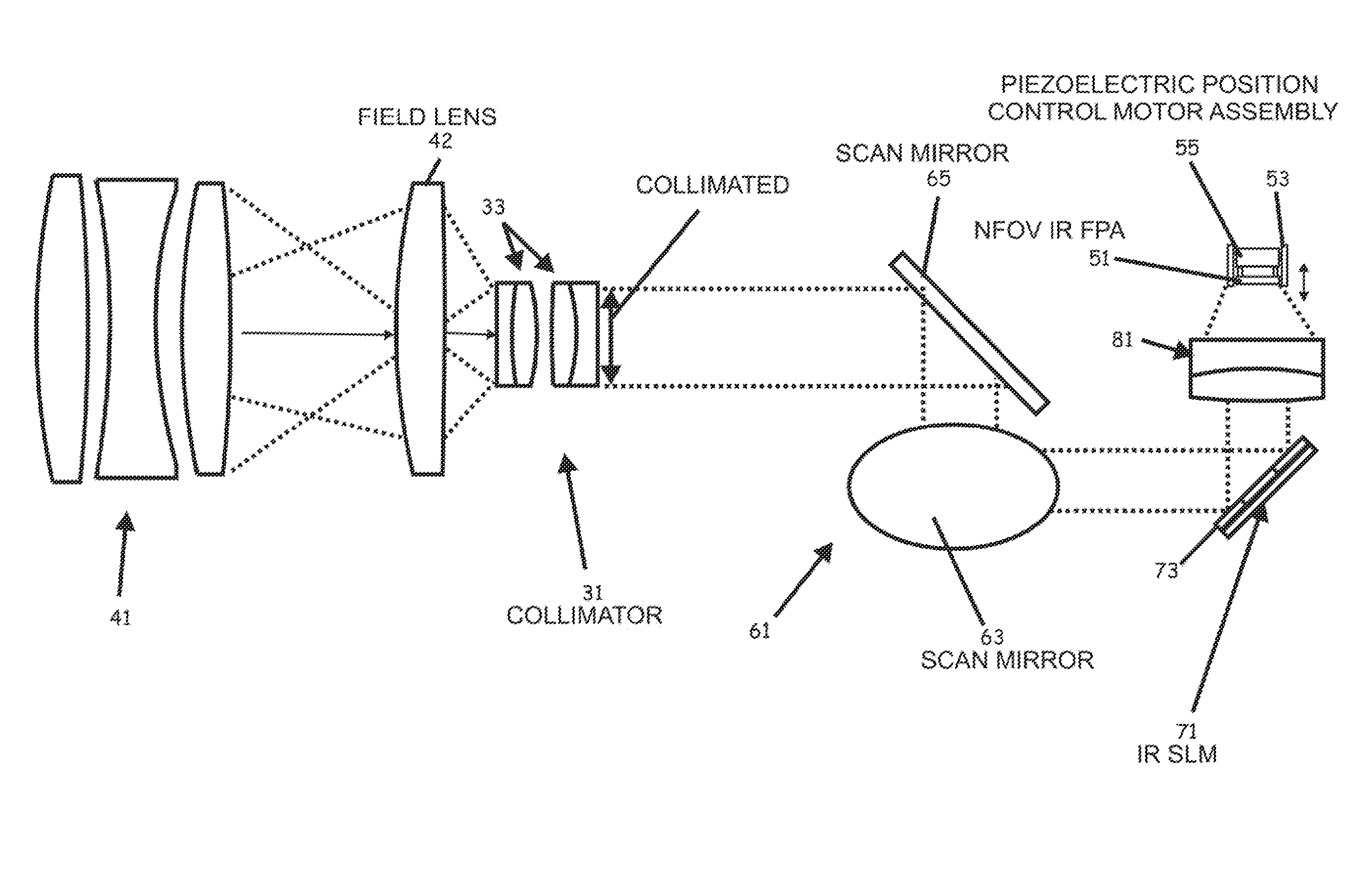
[0019]Various embodiments of the present invention include a
beam splitter to allow the apparatus to simultaneously analyze both wide and narrow fields at the cost of some light. Alternative embodiments of the present invention utilize a mirror which deflects the focused rays of light through a different
optical path after the primary lens of the
sensor system to provide interleaved operation with little loss of light. Various embodiments of the present invention utilize a piezo-electric device or other mechanism to move an
optical detector array along the
optical axis to produced focused and defocused images, quickly and accurately and in such a manner that the distance is know or is easily determined.
[0020]Various embodiments of the present invention advantageously combine use of lowlight electro-optical (TV) camera / shortwave IR sensors and mid-band IR sensors / long wave IR sensors to provide
daytime, nighttime,
bad weather capabilities. Various features can include dual
baud detectors, spatial light modulators to provide adaptive aperture and
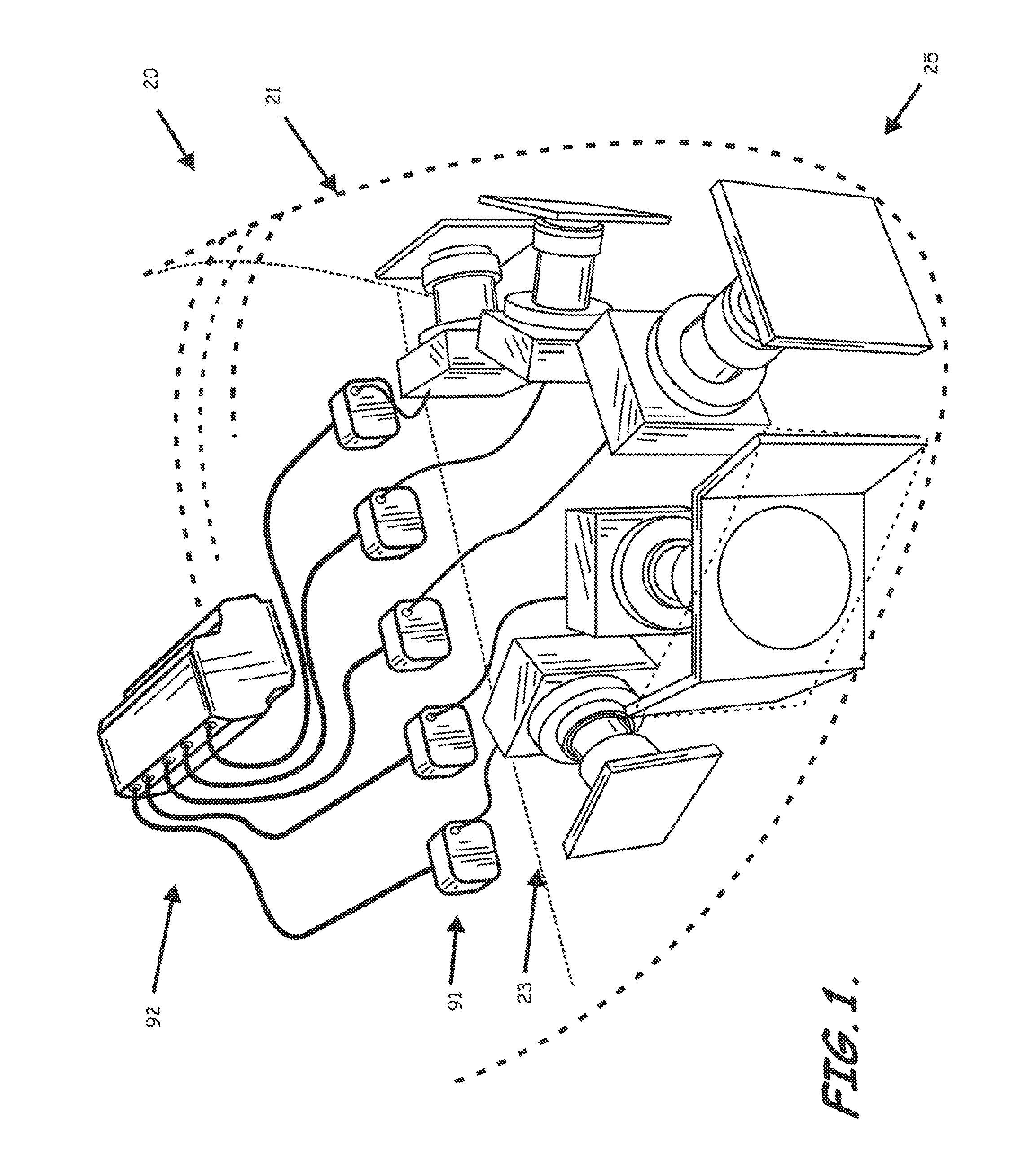
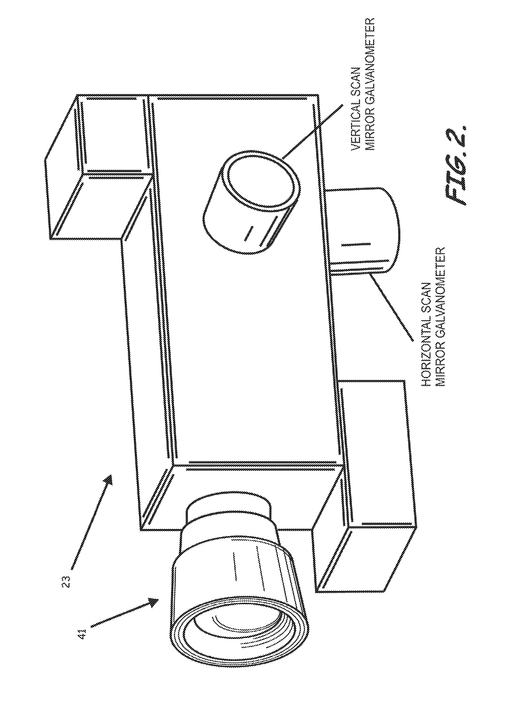
light control, spatial light modulators to reduce the effective image overlap, multiple sensors using multiple fields of view—wide field of view
processing followed by narrow field of view operation, with common
optics using two scanning mirrors, a field of regard of 30 degrees vertically and 44 degrees horizontally for each of, e.g., five sensors to create a ±15 degrees elevation and ±110 degrees
azimuth, and track filtering to eliminate false alarms. According to various embodiments of the present invention, the optical system employs a wide field of view portion having a high
false alarm rate followed by narrow field of view with multiple looks to confirm true targets with good range data and to eliminate false alarms.
[0021]Various embodiments of the present invention provide enhanced range accuracy, passive
image acquisition, subpixel
object detection, multiple fields of view, a wide field of regard coverage, simultaneous multiple fields of view with narrow field of view operation over the entire wide field of view without use of gimbals or motion of vehicle, and / or a sensor control and
image processor which employs an
algorithm capable of range measurements with a single sensor and fixed focus setting which can detect objects smaller than a pixel without need for two cameras.

