
Forward mounted gun sight with illumination apparatus
a backup sight and forward mounted technology, applied in the field of firearms, can solve problems such as blocking some of the user's vision field, and achieve the effects of minimal encumbrance of the weapon, effective light placement, and convenient us
- Summary
- Abstract
- Description
- Claims
- Application Information
AI Technical Summary
Benefits of technology
Problems solved by technology
Method used
Image

Examples
Embodiment Construction
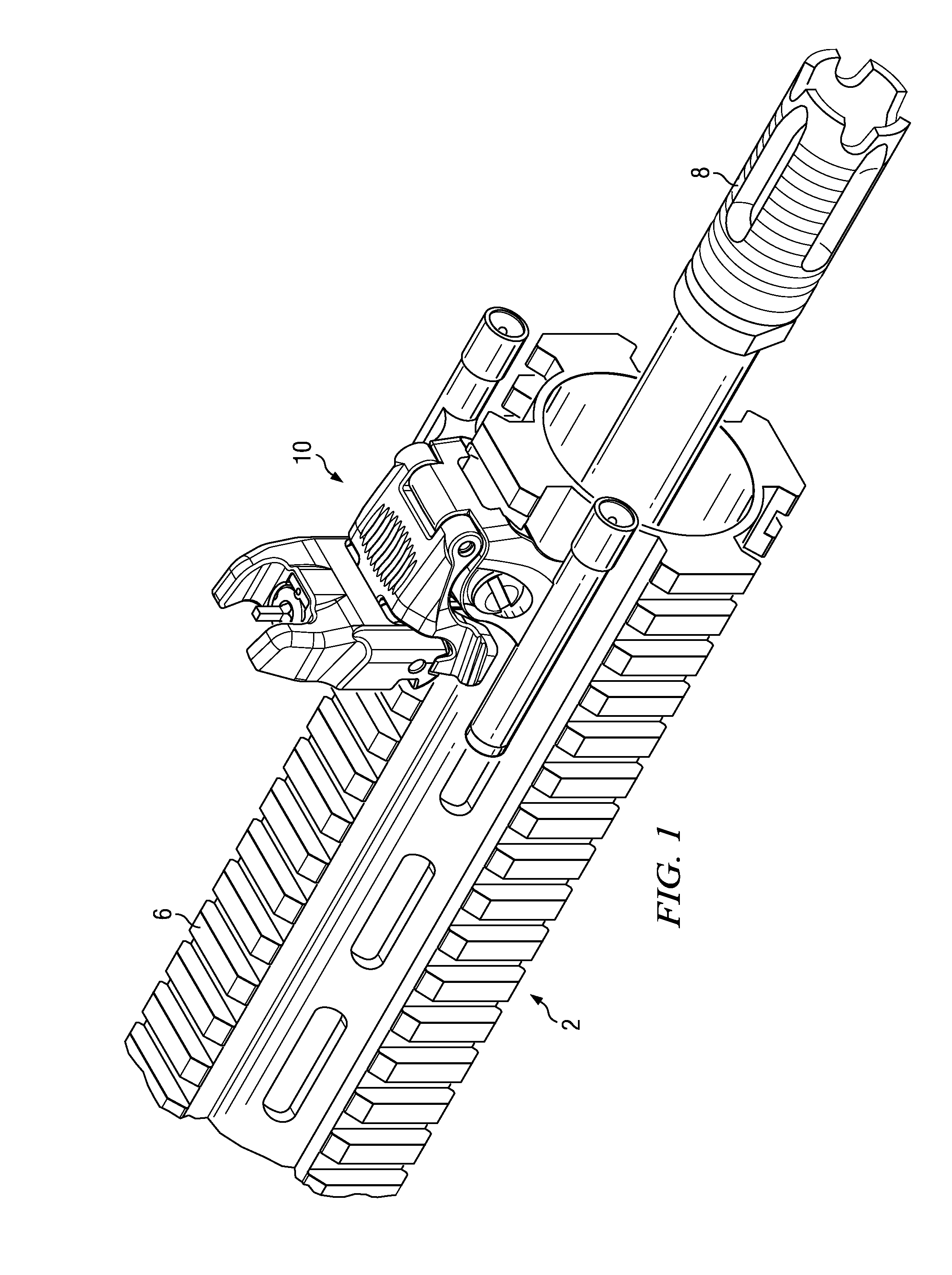
[0018]With reference now to the drawings, the preferred embodiment of the front back-up sight is herein described. It should be noted that the articles “a”, “an”, and “the”, as used in this specification, include plural referents unless the content clearly dictates otherwise.
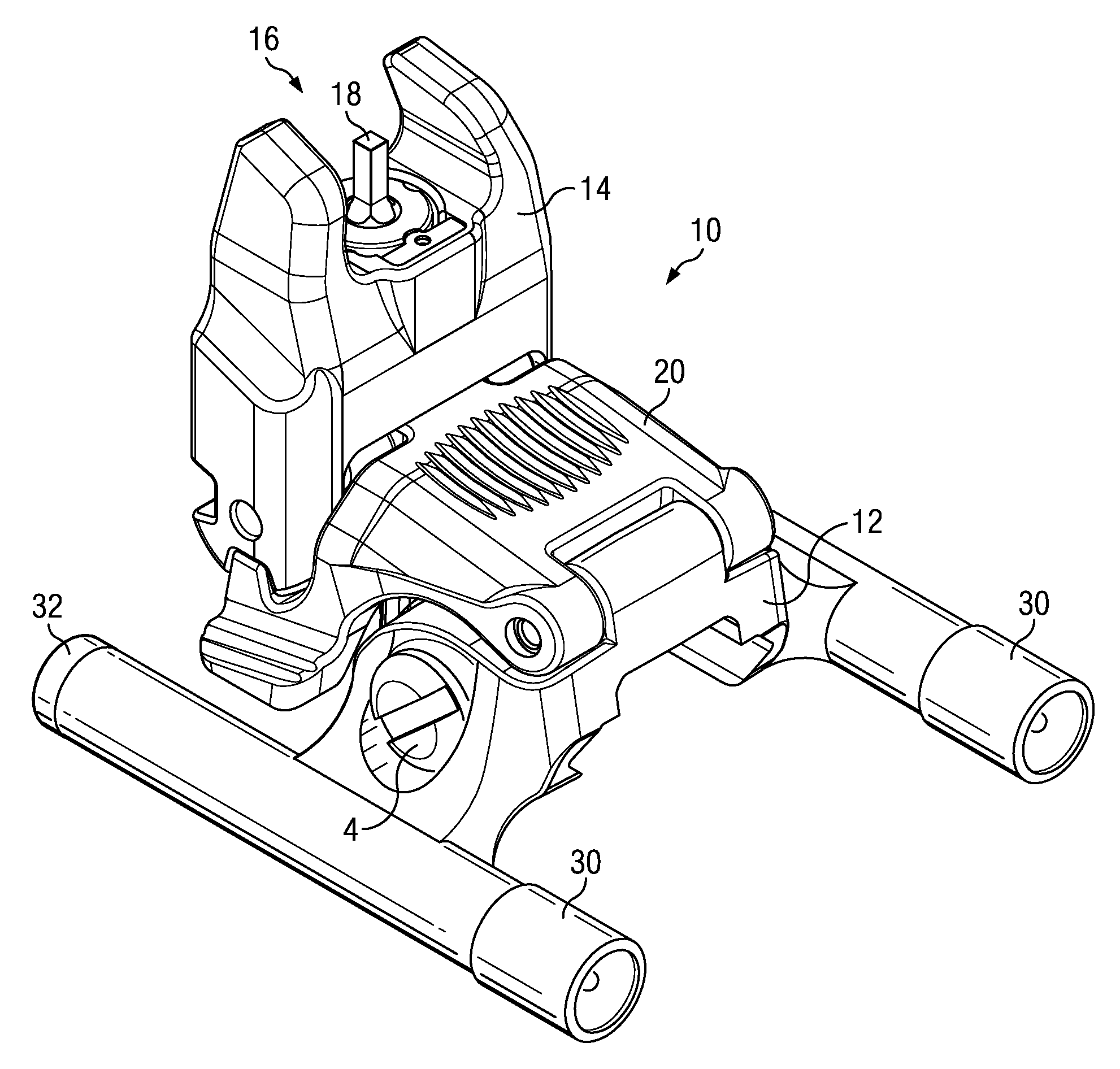
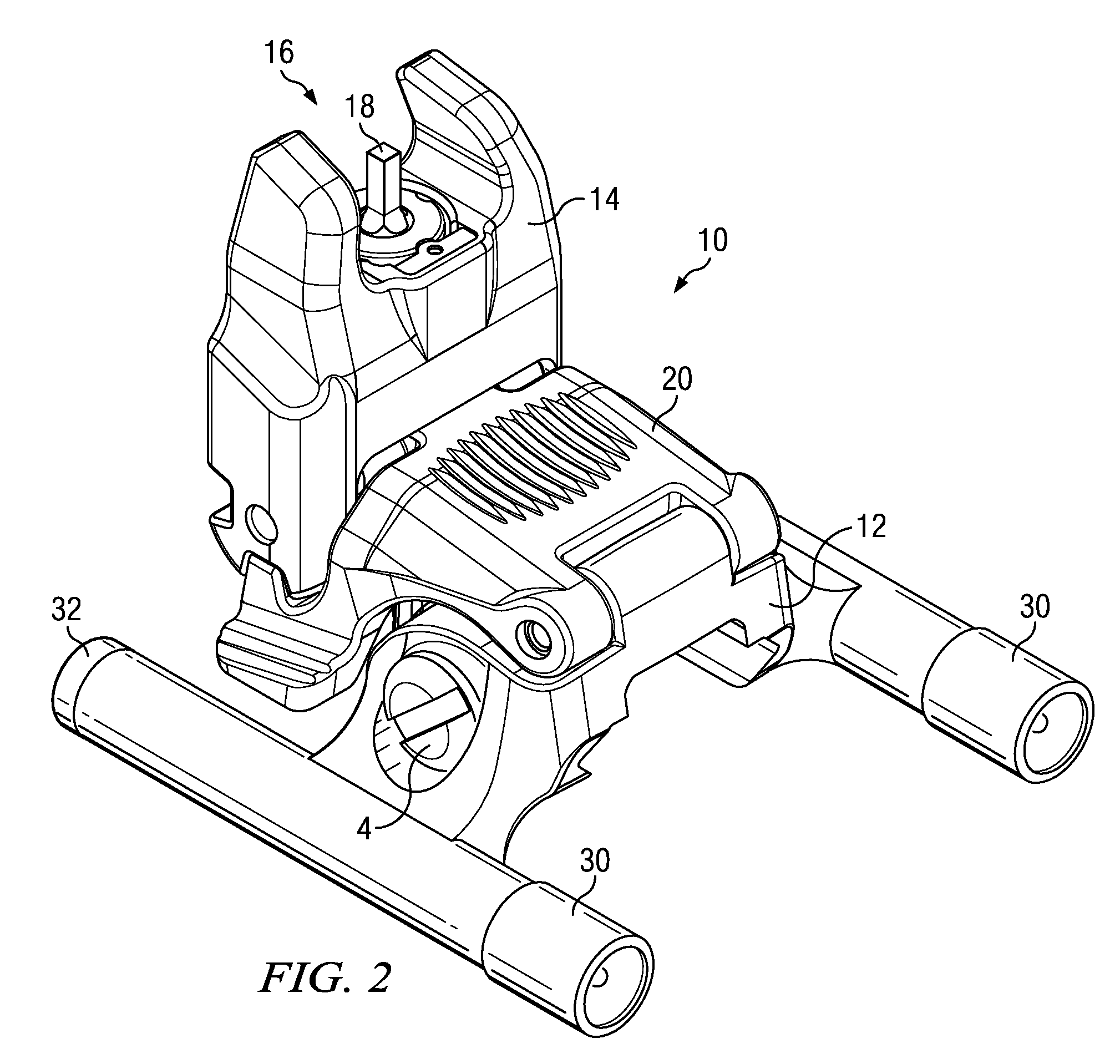
[0019]With reference to FIGS. 3-6, the back-up sight 10 comprises a base 12 and sight housing 14 hingedly connected together. The sight housing is spring-biased 22 (FIG. 6) in the deployed position, as shown in FIG. 4. A latch 20 is also hingedly attached to the base 12. In the depicted embodiment, the latch 20 forms a carapace over base 12 and is hinged at an edge of the base 12 opposite the sight housing 14. Latch 20 features two teeth 24, on opposite sides, and each tooth 24 selectively engages one of a set of two notches 26, 28, each set likewise being on opposite sides of the sight housing 14. While stowed, FIG. 5, latch 20 engages notches 26 and secures the sight housing 14 against the spring bias 22. Upon...
PUM
 Abstract
Description
Claims
Application Information