
Acoustic pseudo-triode characteristic amplification device and acoustic pseudo-triode characteristic push-pull amplification device
a technology of characteristic amplification and push-pull amplification, which is applied in the direction of push-pull amplifiers, phase-splitters, low-frequency amplifiers, etc., can solve the problems of nonlinear loading of speakers and unnatural sound generated by speakers, and achieve the effect of reducing distortion components
- Summary
- Abstract
- Description
- Claims
- Application Information
AI Technical Summary
Benefits of technology
Problems solved by technology
Method used
Image

Examples
first embodiment
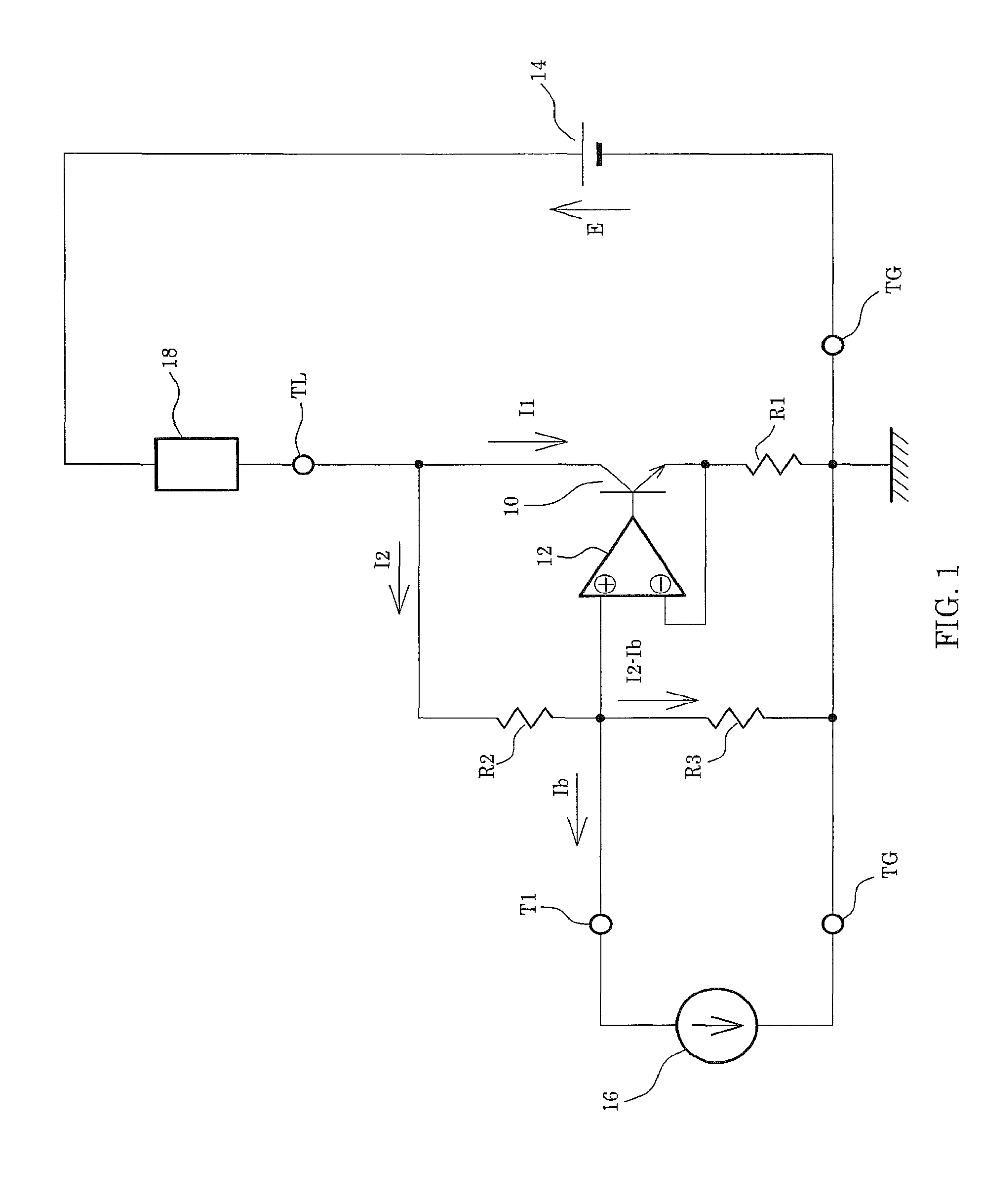
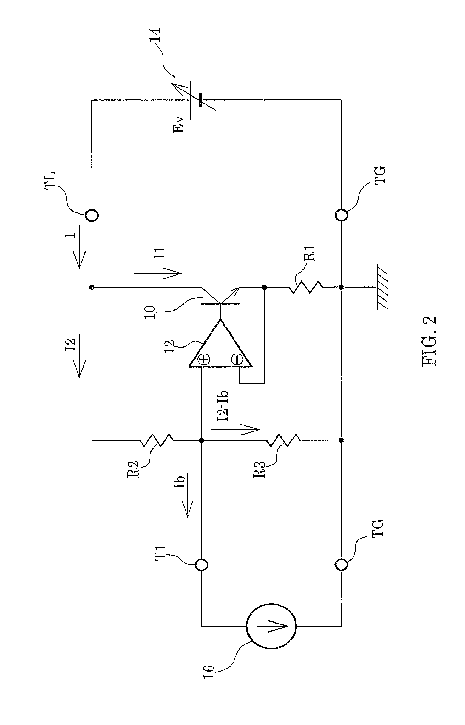
[0025]FIG. 1 shows a configuration of a pseudo-triode characteristic linear amplifier according to a The pseudo-triode characteristic linear amplifier uses a semiconductor element, has a characteristic closely approximating a characteristic of the triode amplifier, and reduces distortion of an output signal. The semiconductor element uses an element which has three electrodes; that is, a first electrode, a second electrode, and a control electrode, where a current flowing between the first and second electrodes varies depending on a signal applied to the control electrode. Here, a circuit configuration using a bipolar transistor as the semiconductor element will be described. In the following description, the bipolar transistor is simply referred to as a transistor.
[0026]An input terminal T1 of the pseudo-triode characteristic linear amplifier is connected to a positive-phase terminal of a differential amplification circuit 12. In addition, a negative-phase terminal of the differen...
second embodiment
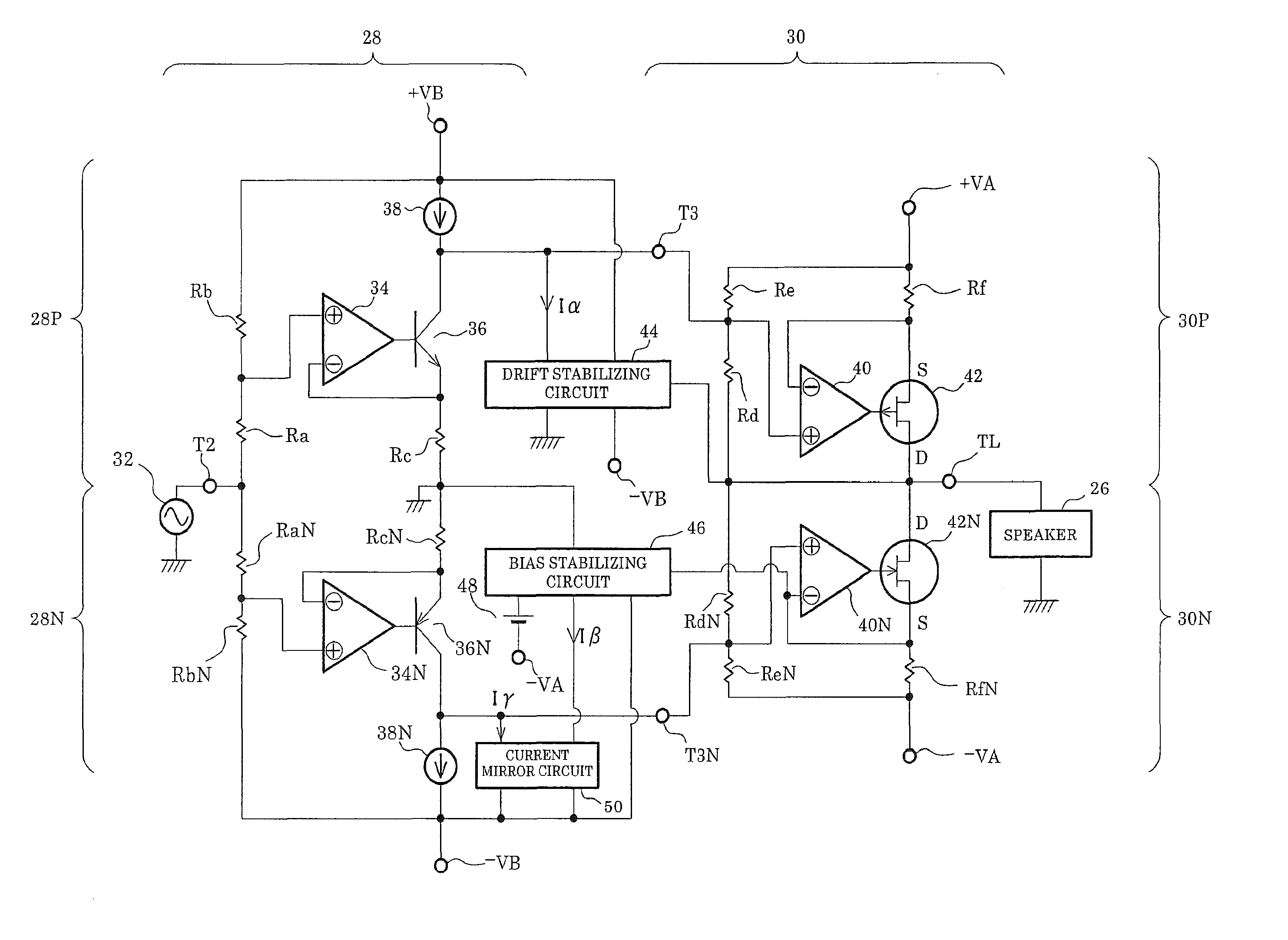
[0047]FIG. 7 shows a configuration of a pseudo-triode characteristic OTL push-pull linear amplifier according to a The amplifier is an OTL (Output Transformer Less) push-pull circuit which is formed by using a pair of circuits having a complementary characteristic in a driving unit 28 and a power amplification unit 30 respectively. The driving unit 28 is applied with a positive DC voltage +VB and a negative DC voltage −VB as a power supply voltage, and the power amplification unit 30 is applied with a positive DC voltage +VA and a negative DC voltage −VA as a power supply voltage.
[0048]The driving unit 28 functions as a current-driving source of the power amplification unit 30. A circuit configuration of a positive power supply driving portion 28P of the driving unit 28, which is driven by the positive DC voltage +VB, will be described. One end of a resistor Ra is connected to an input terminal T2. The other end of the resistor Ra is connected to a positive-phase terminal of a diff...
PUM
 Abstract
Description
Claims
Application Information