Distortion compensating circuit for compensating distortion occurring in power amplifier

a distortion compensation and power amplifier technology, applied in the direction of transmission monitoring, phase-modulated carrier systems, baseband system details, etc., can solve the problems of difficult enhancement of efficiency, high price, and large power consumption, and achieve the effect of enhancing the effect of non-linear distortion compensation and reducing the components of clipping distortion

Active Publication Date: 2005-08-09
NEC CORP
View PDF10 Cites 131 Cited by
  • Summary
  • Abstract
  • Description
  • Claims
  • Application Information

AI Technical Summary

Benefits of technology

[0024]Therefore, an object of the present invention is to provide a distortion compensation circuit which can implement reduction of clipping distortion components with correctly performing error calculation, and greatly enhance the effect of non-linear distortion compensation carried out subsequently.

Problems solved by technology

However, if a power amplifier is designed to have excellent linearity to even remarkably large amplitude components, the scale of the power amplifier is large, the price thereof is high and the power consumption is also large.
With respect to the feed-forward type, it is difficult to enhance the efficiency because it structurally needs an error amplifier.
However, in the conventional pre-distortion type and Cartesian feedback type distortion compensation circuits, the clipping distortion components cannot be compensated.
Furthermore, there is also such a disadvantage that the amplitude compensation when the distortion compensation is carried out causes the signal amplitude after compensation to reach the saturated area of the power amplifier for even instantaneous input amplitude components which are lower than the saturation input in the case of non-compensation by several dB (decibel), thereby increasing clipping distortion, so that the distortion compensation increasing clipping distortion, so that the distortion compensation effect is lowered.
Therefore, by the conventional distortion compensation circuit having the construction as described above, accurate error correction cannot be performed and the distortion compensation cannot be performed with high precision.
The conventional distortion compensation circuit as described above has the disadvantage that the accurate error calculation cannot be performed because the input quadrature baseband signal before the amplitude limitation is carried out and the feedback signal after the amplitude limitation is carried out are compared with each other to perform the error calculation.

Method used


Image

  • Distortion compensating circuit for compensating distortion occurring in power amplifier
  • Distortion compensating circuit for compensating distortion occurring in power amplifier
  • Distortion compensating circuit for compensating distortion occurring in power amplifier

Examples


first embodiment

(First Embodiment)

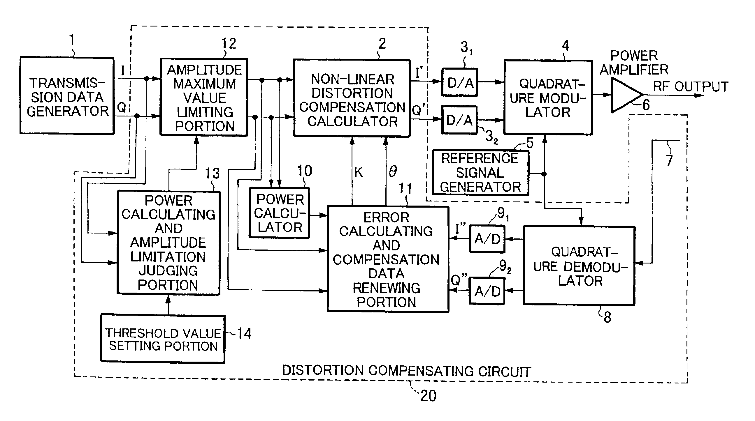
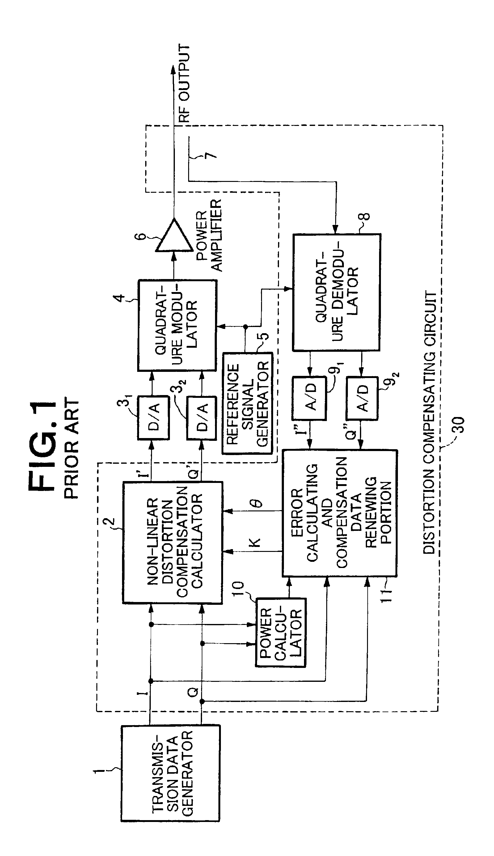
[0050]FIG. 4 is a block diagram showing the construction of a radio transmission device having a distortion compensating circuit according to a first embodiment of the present invention. In FIG. 4, the same parts as the prior art shown in FIG. 1 are represented by the same reference numerals.

[0051]The difference between the radio transmission device of this embodiment and the conventional radio transmission device shown in FIG. 1 resides in that the distortion compensating circuit 30 is replaced by a distortion compensating circuit 20. The distortion compensating circuit 20 of this embodiment is different from the distortion compensating circuit 30 shown in FIG. 1 only in that the distortion compensating circuit 20 is further equipped with amplitude maximum value limiting portion 12, power calculating and amplitude limitation judging portion 13 and threshold value setting portion 14.

[0052]The threshold setting portion 14 sets a predetermined value as a power thresh...

second embodiment

(Second Embodiment)

[0081]Next, a distortion compensating circuit according to a second embodiment of the present invention will be described.

[0082]In the distortion compensating circuit of the first embodiment described above, it is judged on the basis of the power threshold value of the digital quadrature baseband signal whether the amplitude limitation is carried out or not. However, according to this embodiment, it is judged on the basis of the amplitude threshold value of the digital quadrature baseband signal whether the amplitude limitation is carried out or not.

[0083]As shown in FIG. 10, the construction of the distortion compensating circuit according to this embodiment is achieved by replacing the power calculating and amplitude limitation judging portion 13 and the threshold value setting portion 14 in FIGS. 4, 5 with amplitude calculating and amplitude limitation judging portion 23 and threshold value setting portion 24.

[0084]The threshold value setting portion 24 sets a ...


PUM


Abstract

A power calculating and amplitude limitation judging portion 13 calculates the power value x of the digital quadrature baseband signal I, Q from a transmission data generator 1, and compares the power value x with a power threshold value y set by a threshold value setting portion 14 to judge whether amplitude limitation is needed or not. An amplitude maximum limiting portion 12 subjects the quadrature baseband signal from the transmission data generator 1 to the amplitude maximum value limitation based on the judgment result in the power calculating and amplitude limitation judging portion 13. Thereafter, the digital quadrature baseband signal which has been subjected to the amplitude maximum value limitation by the amplitude maximum value limiting portion 12 is subjected to the distortion compensation using complex multiplication based on the distortion compensation data by a non-linear distortion compensation calculator 2.

Description

BACKGROUND OF THE INVENTION[0001]1. Field of the Invention[0002]The present invention relates to a distortion compensating circuit that is usable for a radio transmission device of a base station or the like in a wireless communication system and serves to compensate distortion occurring in amplifying means such as a power amplifier or the like.[0003]2. Description of the Related Art[0004]In order to suppress adjacent channel leakage power, it is ideal for a radio transmission device in a wireless communication system to use a power amplifier having excellent linearity in all the amplitude components. However, if a power amplifier is designed to have excellent linearity to even remarkably large amplitude components, the scale of the power amplifier is large, the price thereof is high and the power consumption is also large. Therefore, there may be such a case that a power amplifier having excellent linearity to small amplitude components, but having non-linearity to large amplitude ...

Claims


Application Information

Patent Timeline
Patent Type & Authority Patents(United States)
IPC IPC(8): H03F1/32H04J13/00H04L27/20H04L27/36
CPCH03F1/3247H03F1/3294
Inventor DOI, YOSHIAKI
Owner NEC CORP
Why Eureka
Try Eureka