System and method for evaluating changes in the efficiency of an HVAC system

a technology of hvac system and efficiency, applied in the field of thermostatic hvac control, can solve the problems of heating system overheating the rest of the house, wasting considerable energy, and too cold the rest of the home, so as to reduce energy use and increase comfor

Active Publication Date: 2011-09-13
ECOFACTOR
View PDF102 Cites 299 Cited by
  • Summary
  • Abstract
  • Description
  • Claims
  • Application Information

AI Technical Summary

Benefits of technology

[0009]There are many other sources of information that could be used to increase comfort, decrease energy use, or both. For example, outside temperature and humidity strongly affect subjective comfort. On a 95 degree, 90 percent humidity day in August, when people tend to dress in lightweight clothing, a house cooled to 70 degrees will feel cool or even uncomfortably cold. On a below-freezing day in January, when people tend to wear sweaters and heavier clothes, that same 70 degree home will feel too warm. It would therefore be advantageous for a thermostat system to automatically incorporate information about external weather conditions when setting the desired temperature.
[0011]These problems can be reduced or eliminated through use of additional remote temperature sensors connected to the thermostat's control circuitry. However, such systems require additional hardware, additional thermostat complexity, and skilled installation and configuration.
[0015]The cost to an electric utility to produce power varies over time. Indeed, the cost of production between low demand and peak demand periods can vary by as much as an order of magnitude. Traditionally, residential customers paid the same price regardless of time or the cost to produce. Thus consumers have had little financial incentive to reduce consumption during periods of high demand and high production cost. Many electric utilities are now seeking to bring various forms of variable rates to the retail energy markets. Under such schemes, consumers can reduce costs by taking into account not just how much energy they use, but when they use it.
[0016]Thus many consumers now can see real benefits from optimizing not just the total number of kilowatt-hours of electricity consumed, but also optimizing when it is used. The optimum strategy for energy use over time will vary based upon many variables, one of which is the thermal mass of the structure being heated or cooled. In a structure with high thermal mass, heating and cooling can effectively be shifted away from high cost periods to lower cost “shoulder” periods with little or no effect on comfort. If, for example, a utility charges much higher rates on hot summer afternoons, it is likely that pre-cooling a high-thermal mass structure just before the high-cost period and then shutting down the air conditioning during the peak will allow the house to remain comfortable. But in a house with low thermal mass, the benefits of pre-cooling will quickly dissipate, and the house will rapidly become uncomfortable if the air conditioning is shut off. Thus it would be advantageous for a temperature control system to take thermal mass into account when setting desired temperatures.
[0018]Most of these problems are likely to manifest themselves in the form of higher energy bills. But the “signature” of each different problem can be discerned from the way in which each such problem affects the cycle times of a given HVAC system over time and relative to weather conditions and the performance of other HVAC systems in other houses. If two otherwise identical houses are located next door to each other and have gas furnaces, but one is rated at 50,000 BTUs and the other is rated at 100,000 BTUs, the cycle times for the higher-capacity furnace should be shorter than for the lower-capacity unit. If both of those same houses have identical furnaces, but one has a clogged filter, the cycle times should be longer in the house with the clogged filter. Because cycling of the HVAC system is controlled by the thermostat, those differences in cycle time would be reflected in the data sensed by and control signals generated by the thermostat. It would be advantageous for a thermostat system to be able to use that information to diagnose problems and make recommendations based upon that data.
[0024]Combining these data sources will also allow the server to calculate the effective thermal mass of the structures conditioned by those thermostats. By combining data from multiple thermostats in a given neighborhood, the system can correct for flaws in the location of a given thermostat, and can evaluate the efficiency of a given system, as well as assist in the diagnosis of problems and malfunctions in such systems.

Problems solved by technology

But there are many reasons and circumstances in which that will not be the case.
This could cause the thermostat to sense that the local ambient temperature is extremely high, and as a result signal the A / C to run too long, making the rest of the home too cold, and wasting considerable energy.
In such a scenario, the thermostat is likely to (correctly) report cold temperatures in the winter, leading the heating system to overheat the rest of the house and waste considerable energy.
However, such systems require additional hardware, additional thermostat complexity, and skilled installation and configuration.

Method used


Image

  • System and method for evaluating changes in the efficiency of an HVAC system
  • System and method for evaluating changes in the efficiency of an HVAC system
  • System and method for evaluating changes in the efficiency of an HVAC system

Examples


Embodiment Construction

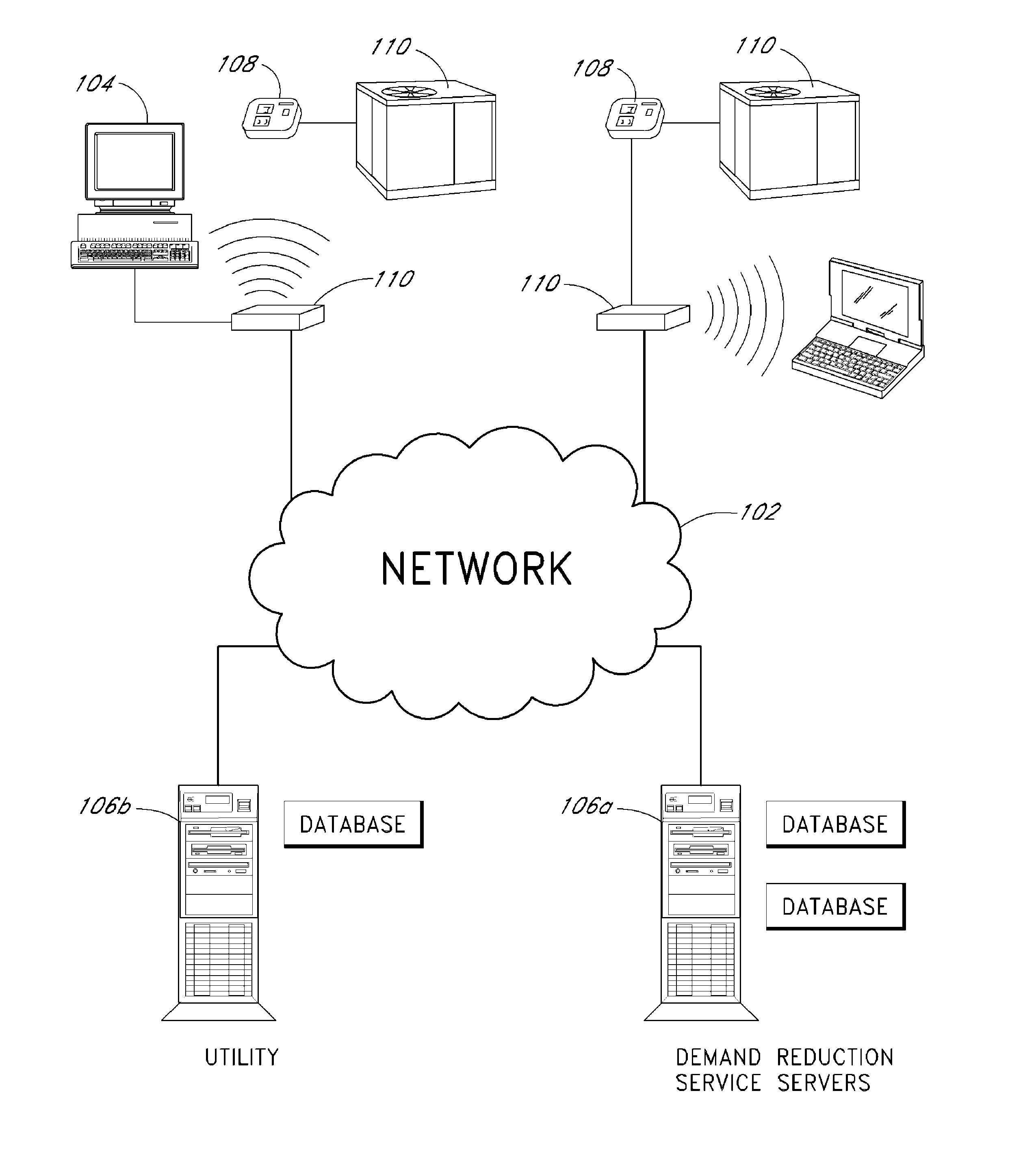
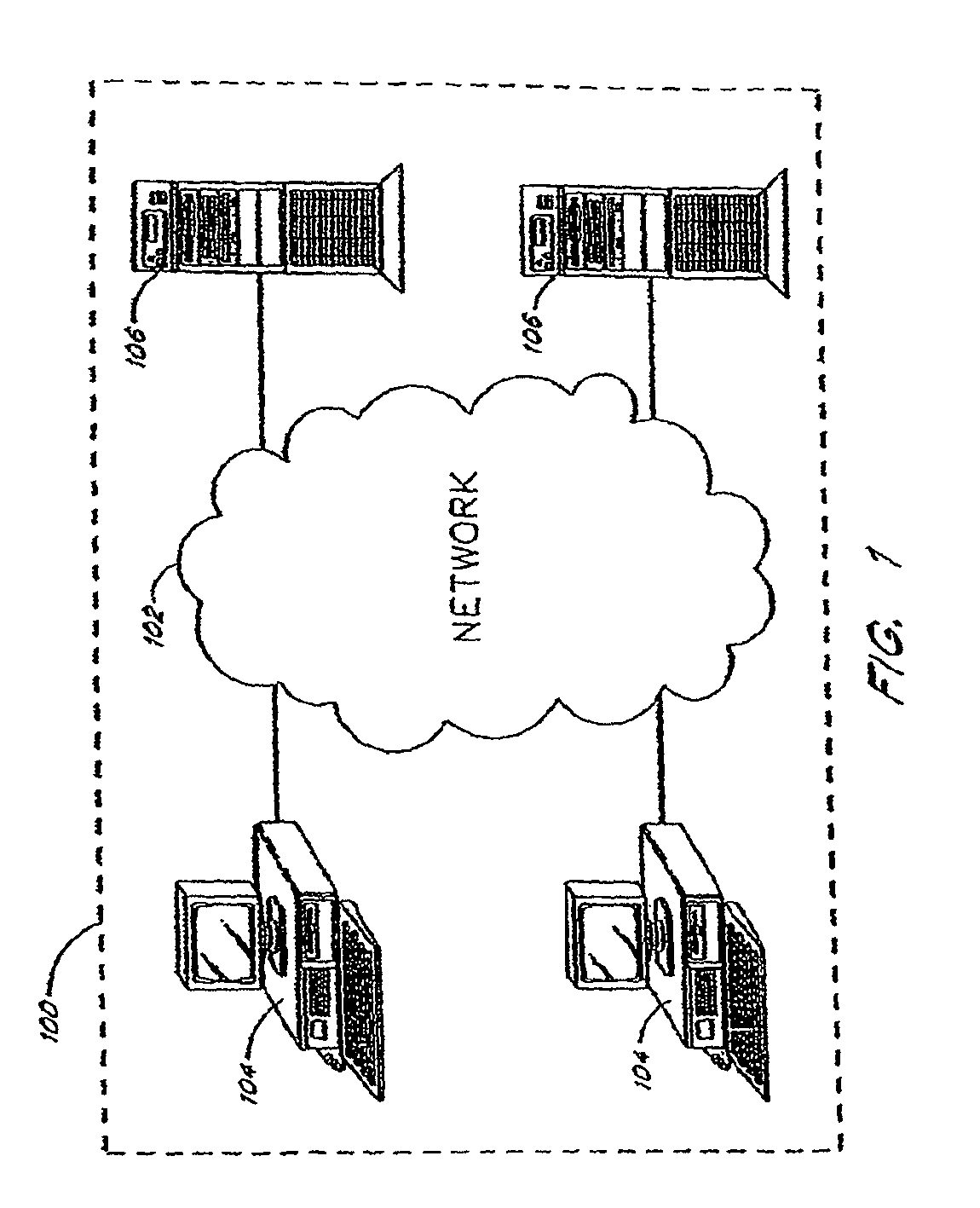
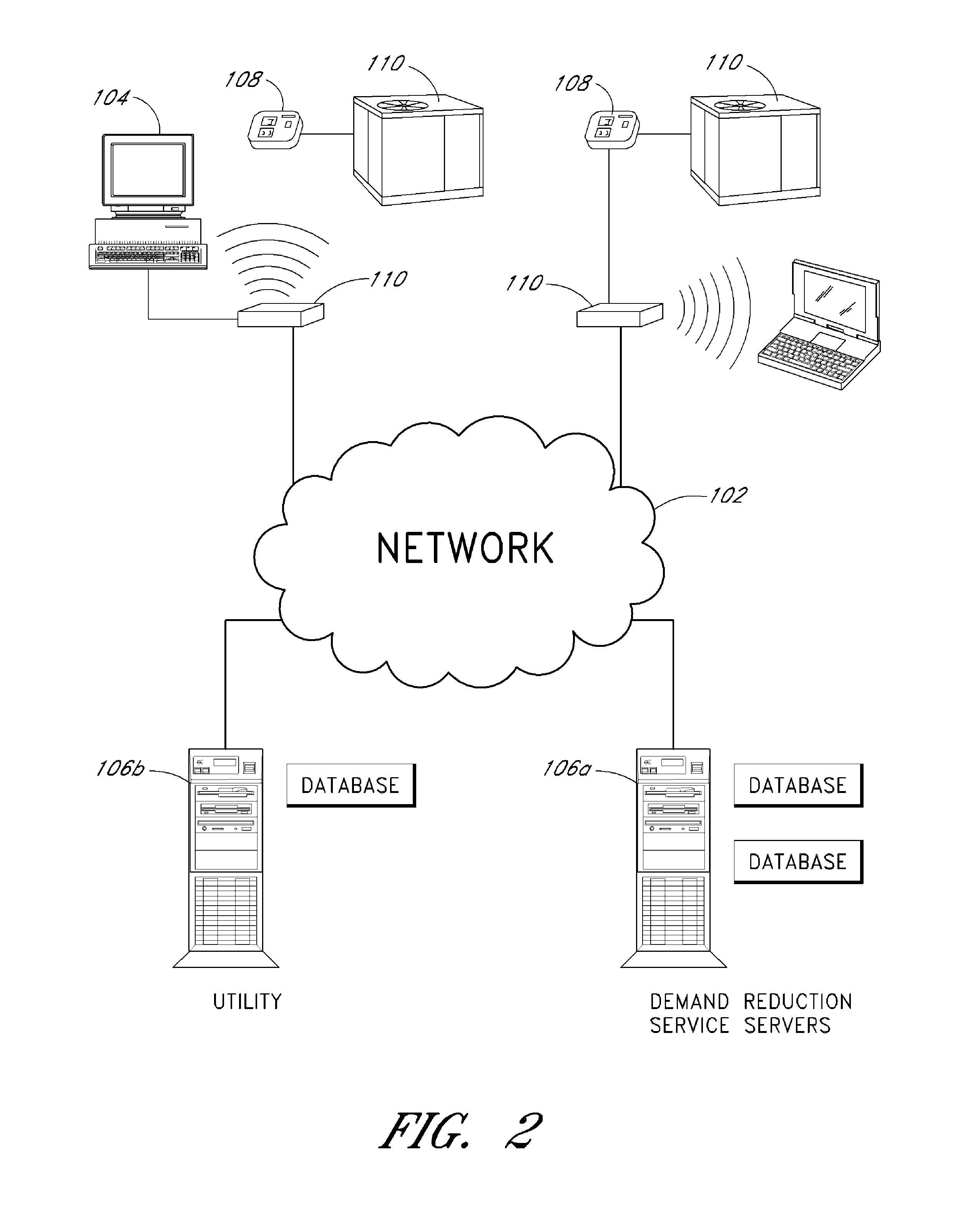
[0039]FIG. 1 shows an example of an overall environment 100 in which an embodiment of the invention may be used. The environment 100 includes an interactive communication network 102 with computers 104 connected thereto. Also connected to network 102 are one or more server computers 106, which store information and make the information available to computers 104. The network 102 allows communication between and among the computers 104 and 106.

[0040]Presently preferred network 102 comprises a collection of interconnected public and / or private networks that are linked to together by a set of standard protocols to form a distributed network. While network 102 is intended to refer to what is now commonly referred to as the Internet, it is also intended to encompass variations which may be made in the future, including changes additions to existing standard protocols.

[0041]When a user of the subject invention wishes to access information on network 102, the buyer initiates connection fro...


PUM

PropertyMeasurementUnit
humidityaaaaaaaaaa
temperatureaaaaaaaaaa
temperaturesaaaaaaaaaa

Abstract

The invention comprises systems and methods for evaluating changes in the operational efficiency of an HVAC system over time. The climate control system obtains temperature measurements from at least a first location conditioned by the climate system, and status of said HVAC system. One or more processors receives measurements of outside temperatures from at least one source other than said HVAC system and compares said temperature measurements from said first location with expected temperature measurements. The expected temperature measurements are based at least in part upon past temperature measurements.

Description

CROSS-REFERENCE TO RELATED APPLICATIONS[0001]This application claims priority to U.S. Provisional Application No. 60 / 994,011, filed Sep. 17, 2007, the entirety of which is incorporated herein by reference and is to be considered part of this specification.BACKGROUND OF THE INVENTION[0002]1. Field of the Invention[0003]This invention relates to the use of thermostatic HVAC controls that are connected to a computer network. More specifically, communicating thermostats are combined with a computer network in order to evaluate changes in the operational efficiency of an HVAC system over time.[0004]2. Background[0005]Climate control systems such as heating and cooling systems for buildings (heating, ventilation and cooling, or HVAC systems) have been controlled for decades by thermostats. At the most basic level, a thermostat includes a means to allow a user to set a desired temperature, a means to sense actual temperature, and a means to signal the heating and / or cooling devices to turn...

Claims


Application Information

Patent Timeline
Patent Type & Authority Patents(United States)
IPC IPC(8): G06F15/00G01K1/00
CPCF24F11/0086G01K13/00F24F2011/0058F24F11/30F24F2130/00F24F2130/10F24F11/52F24F11/47F24F11/63G01M99/005
Inventor STEINBERG, JOHN DOUGLASHUBLOU, SCOTT DOUGLAS
Owner ECOFACTOR
Why Eureka
Try Eureka