Surgical instrument having a multiple rate directional switching mechanism

a switching mechanism and surgical instrument technology, applied in the field of surgical staplers, can solve the problems of not being able to partially retract the cutting member, devices which perform both functions in the same trigger actuation are often exceedingly difficult to operate, and not affording the surgeon an opportunity

Active Publication Date: 2013-09-17
CILAG GMBH INT
View PDF2415 Cites 1424 Cited by
  • Summary
  • Abstract
  • Description
  • Claims
  • Application Information

AI Technical Summary

Problems solved by technology

Such staplers, however, are unable to partially retract the cutting member and, as a result, the cutting member must be fully retracted before it can be readvanced.
While suitable in some circumstances, devices which perform both functions in the same trigger actuation are often exceedingly difficult to operate owing to the high degree of force required to actuate the trigger.
Furthermore, such devices, as they close the jaw member and deploy staples in the same trigger actuation, do not afford the surgeon with an opportunity to evaluate the position of the closed jaw member and reposition the jaw member before the staples are deployed into the soft tissue.

Method used


Image

  • Surgical instrument having a multiple rate directional switching mechanism
  • Surgical instrument having a multiple rate directional switching mechanism
  • Surgical instrument having a multiple rate directional switching mechanism

Examples


Embodiment Construction

[0044]Certain exemplary embodiments will now be described to provide an overall understanding of the principles of the structure, function, manufacture, and use of the devices and methods disclosed herein. One or more examples of these embodiments are illustrated in the accompanying drawings. Those of ordinary skill in the art will understand that the devices and methods specifically described herein and illustrated in the accompanying drawings are non-limiting exemplary embodiments and that the scope of the various embodiments of the present invention is defined solely by the claims. The features illustrated or described in connection with one exemplary embodiment may be combined with the features of other embodiments. Such modifications and variations are intended to be included within the scope of the present invention.

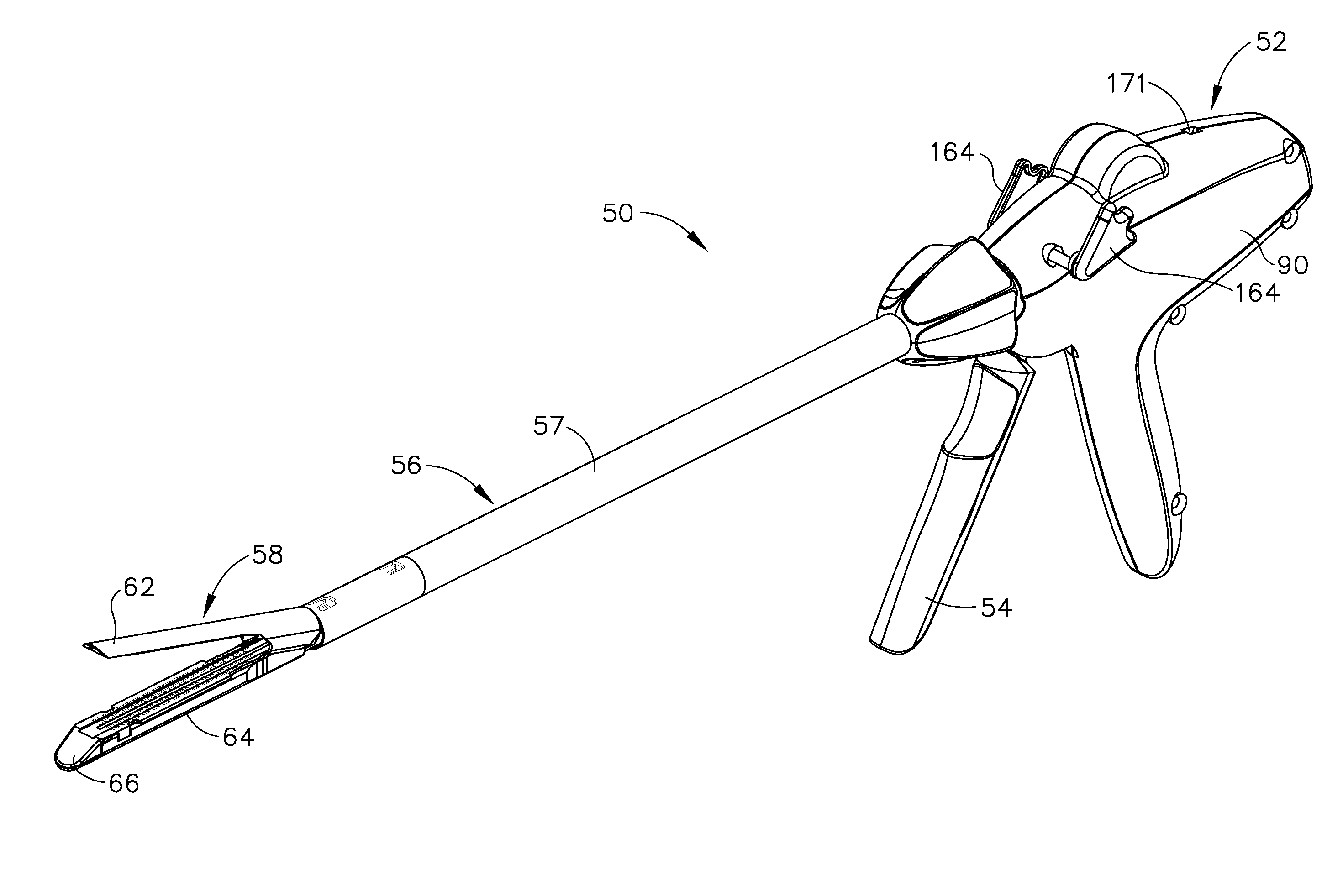
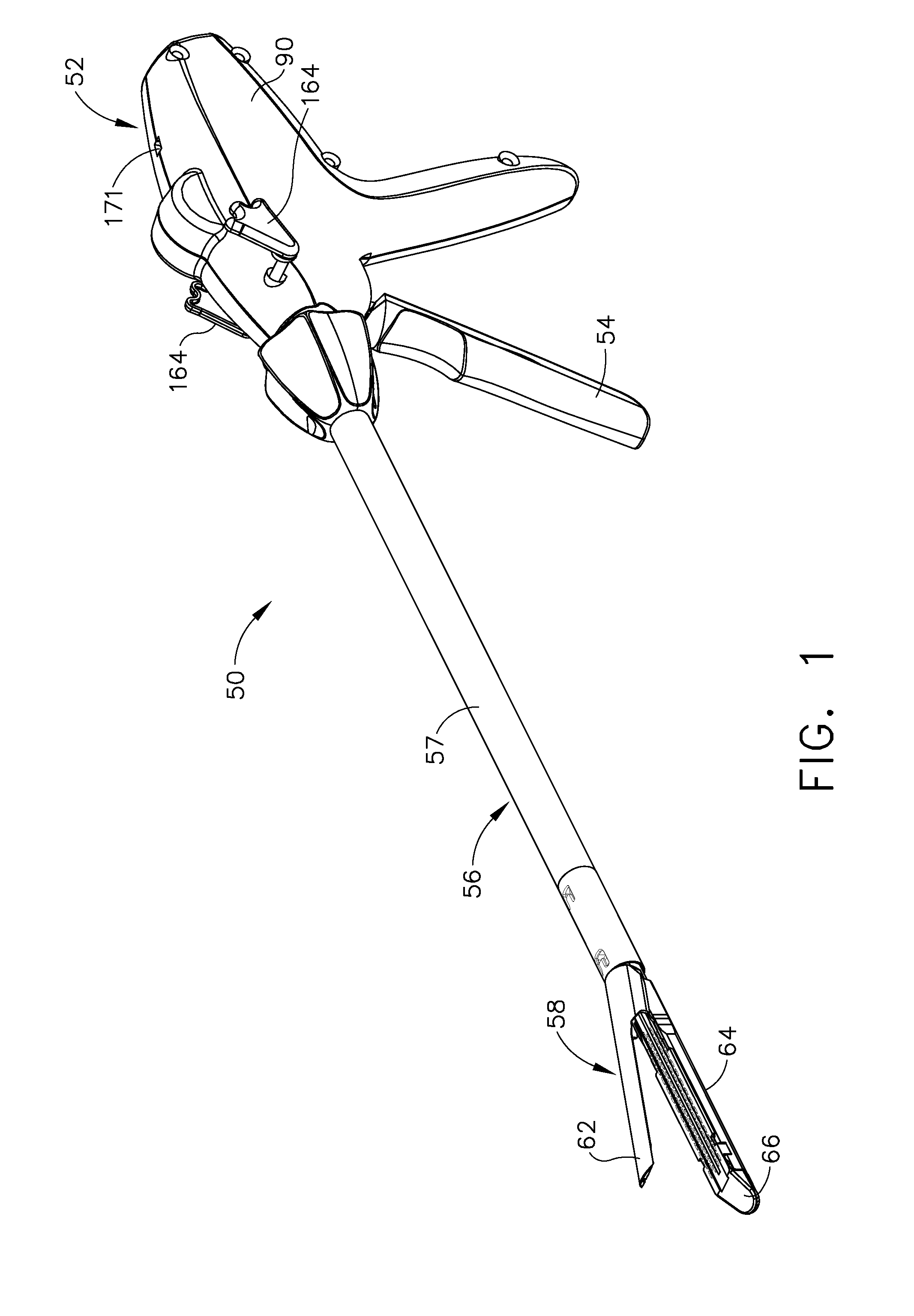
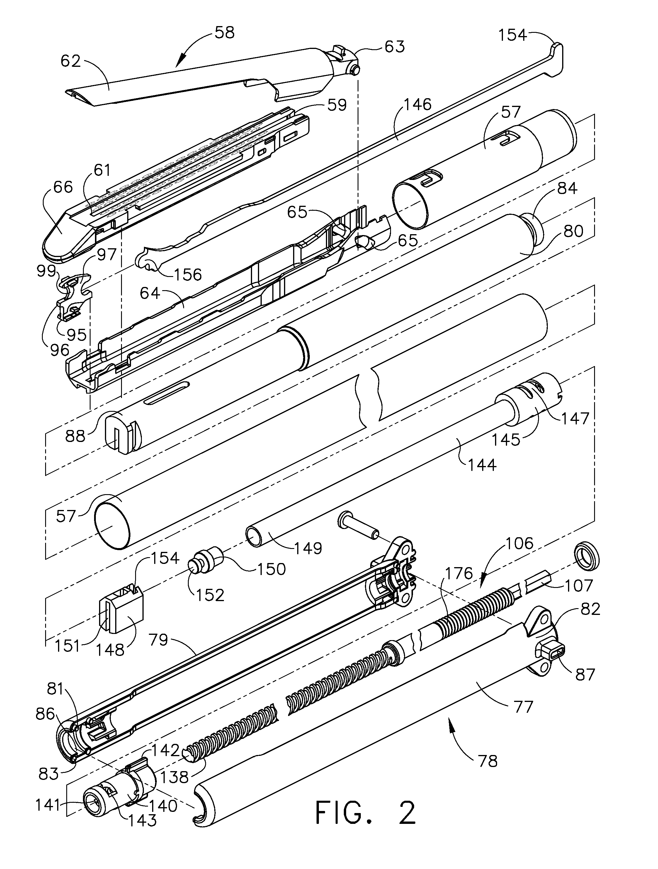
[0045]In various embodiments, a surgical instrument in accordance with the present invention can include systems for inserting surgical staples into soft tissue, f...


PUM

PropertyMeasurementUnit
distanceaaaaaaaaaa
degree of forceaaaaaaaaaa
perimeteraaaaaaaaaa

Abstract

A surgical instrument having a remotely controllable user interface, and a firing drive configured to generate a rotary firing motion upon a first actuation of the remotely controllable user interface and a rotary refraction motion upon an other actuation of remotely controllable user interface. The instrument is such that when the remotely controllable user interface operates a first drive member, the first actuation advances a cutting member a first distance, wherein, when the remotely controllable user interface operates a second drive member, the other actuation retracts the cutting member a second distance, and wherein the second distance is greater than the first distance.

Description

CROSS-REFERENCE TO RELATED APPLICATIONS[0001]This present application is a continuation-in-part which claims benefit of U.S. patent application Ser. No. 11 / 810,015, June 4, 2007, now U.S. Pat. No. 7,905,380, entitled: “Surgical Instrument Having a Multiple Rate Directional Switching Mechanism”; The present application is related to the following commonly-owned U.S. Patent Applications filed concurrently herewith, and which are hereby incorporated by reference in their entirety.[0002](1) U.S. patent application Ser. No. 11 / 810,016, entitled “SURGICAL INSTRUMENT HAVING A DIRECTIONAL SWITCHING MECHANISM”, Issued on Nov. 16, 2010 as U.S. Pat. No. 7,832,408; and[0003](2) U.S. patent application Ser. No. 11 / 809,935, entitled “SURGICAL INSTRUMENT HAVING A COMMON TRIGGER FOR ACTUATING AN END EFFECTOR CLOSING SYSTEM AND A STAPLE FIRING SYSTEM”, Issue on Oct. 26, 2010 as U.S. Pat. No. 7,819,299.BACKGROUND[0004]1. Field of the Invention[0005]The present invention generally relates to surgical ...

Claims


Application Information

Patent Timeline
Patent Type & Authority Patents(United States)
IPC IPC(8): A61B17/32A61L2/00
CPCA61B17/07207A61B2017/00212A61B2017/00367A61B2019/4857A61B2017/2923A61B2017/2925A61B2017/07285A61B2090/0811F04C2270/0421
Inventor SHELTON, IV, FREDERICK E.
Owner CILAG GMBH INT
Why Eureka
Try Eureka