External user interface for head worn computing

a user interface and computing technology, applied in the field of head worn computing, can solve the problems of many problems in the wearable computing field

Inactive Publication Date: 2016-01-28
OSTERHOUT GROUP INC
View PDF8 Cites 129 Cited by
  • Summary
  • Abstract
  • Description
  • Claims
  • Application Information

AI Technical Summary

Benefits of technology

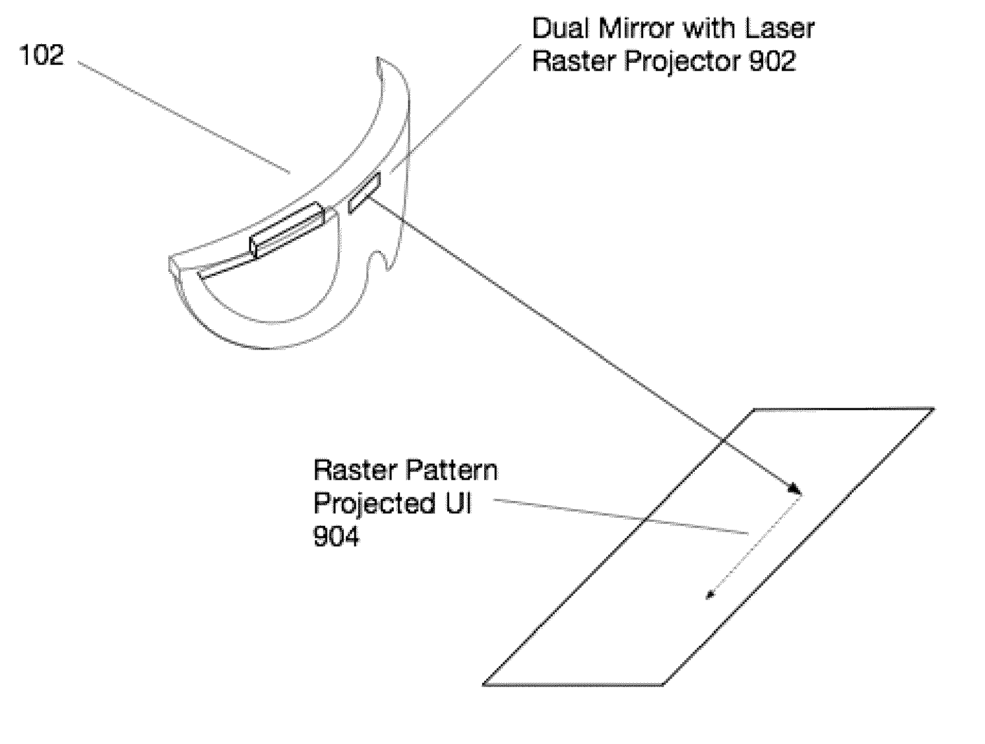
[0008]Aspects of the present invention relate to the projection of imagery from a head-worn computer, wherein a projector with x-y control and

Problems solved by technology

Many problems persist in the wearable computing field that ne

Method used


Image

  • External user interface for head worn computing
  • External user interface for head worn computing
  • External user interface for head worn computing

Examples


Embodiment Construction

)

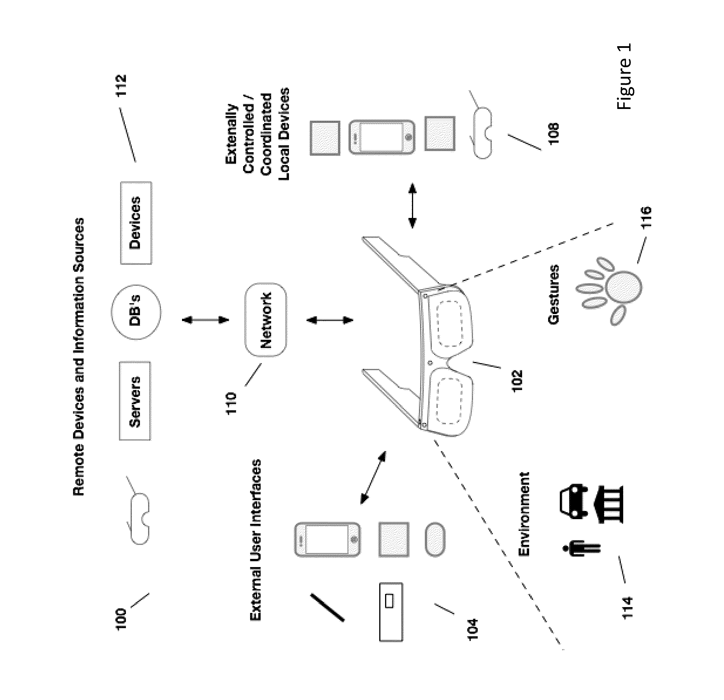
[0021]Aspects of the present invention relate to head-worn computing (“HWC”) systems. HWC involves, in some instances, a system that mimics the appearance of head-worn glasses or sunglasses. The glasses may be a fully developed computing platform, such as including computer displays presented in each of the lenses of the glasses to the eyes of the user. In embodiments, the lenses and displays may be configured to allow a person wearing the glasses to see the environment through the lenses while also seeing, simultaneously, digital imagery, which forms an overlaid image that is perceived by the person as a digitally augmented image of the environment, or augmented reality (“AR”).

[0022]HWC involves more than just placing a computing system on a person's head. The system may need to be designed as a lightweight, compact and fully functional computer display, such as wherein the computer display includes a high resolution digital display that provides a high level of emersion comprised...


PUM


Abstract

Aspects of the present invention relate to the projection of imagery from a head-worn computer, wherein a projector with x-y control and a laser are mounted in the head-worn computer and positioned to project a raster style interactive user interface image onto a nearby surface.

Description

CROSS REFERENCE TO RELATED APPLICATIONS[0001]This application claims the benefit of priority to and is a continuation-in-part of the following U.S. patent application:[0002]U.S. non-provisional application Ser. No. 14 / 337,346, entitled EXTERNAL USER INTERFACE FOR HEAD WORN COMPUTING, filed Jul. 22, 2014.[0003]The above application is incorporated herein by reference in its entirety.BACKGROUND[0004]1. Field of Invention[0005]This invention relates to head worn computing. More particularly, this invention relates to external user interfaces related to head worn computing.[0006]2. Description of Related Art[0007]Wearable computing systems have been developed and are beginning to be commercialized. Many problems persist in the wearable computing field that need to be resolved to make them meet the demands of the market.SUMMARY[0008]Aspects of the present invention relate to the projection of imagery from a head-worn computer, wherein a projector with x-y control and a laser are mounted ...

Claims


Application Information

Patent Timeline
IPC IPC(8): G09G5/38G02B27/00G02B27/01G06T19/00H04N13/363
CPCG09G5/38G02B27/0172G02B2027/0178G06T19/006G02B27/0093G02B2027/0138G06F3/14G06F3/147G09G2354/00H04N9/3129H04N9/3173H04N9/3185H04N9/3194G06F3/013G06F3/03545G02B27/017G06F1/163G06F3/012G02B2027/014G02B2027/0141G02B2027/0198H04N9/3179H04N13/363G06V30/1423G01B11/254
Inventor OSTERHOUT, RALPH F.BORDER, JOHN N.HADDICK, JOHN D.NORTRUP, EDWARD H.
Owner OSTERHOUT GROUP INC
Why Eureka
Try Eureka