Dispensing channel pump

a technology of pump and channel pump, which is applied in the direction of pliable tubular containers, single-unit devices, containers, etc., to achieve the effect of promoting convenient access and timely us

Inactive Publication Date: 2013-10-15
HARPER WILLIAM A
View PDF19 Cites 5 Cited by
  • Summary
  • Abstract
  • Description
  • Claims
  • Application Information

AI Technical Summary

Benefits of technology

[0004]The present invention recognizes the abundance of the prior art and contributes a specific advancement over that art. Accordingly it is a particular intent of the present invention to provide a simple internal pump mechanism exemplified by placing such a pump within a pouch reservoir forming a liquid dispenser of such size and shape as to be carried in a pocket or hung about a neck and thus promoting convenient access to and timely use of the entire liquid product held within. Specifically, the pump located inside the liquid reservoir does not employ a one-way inlet valve for controlling liquid entering the pump chamber from the reservoir chamber as taught by the prior art represented by various check-ball designs. Further, the pump action of the current invention does not employ a one-way inlet mechanism controlling liquid entering the pump chamber as taught in prior art; nor does the current disclosure teach the teat pinch / squeeze technique found in other art. Instead, the flexible fluidic passage between the reservoir and pump chamber is located so a portion of the passageway channel is pressed shut by direct linear finger pressure so that, because the channel is layered with the pump chamber, continued finger pressure is transmitted to the adjoining pump chamber so as to pressurize the fluid within the pump chamber by volumetric distortion which is then forced thru a one-way exit valve for dispersal. When the channel becomes unblocked absent the external pressure holding the channel walls together and the pump chamber returns to its original undistorted volume, reservoir fluid refills the chamber with fluid moving thru the unblocked channel from the reservoir. Because the channel and pump chamber are arrayed each on the other in a layered fashion a tactile and / or visual cuing means indicating application of finger pressure on a particular location is helpful to properly perform a pump cycle action requiring the closure of the channel and pressurizing of the pump chamber.
[0005]This simple pump, essentially a combination of several film walls, an exit valve, and a channel / chamber layered array, requires a minimal number of components and materials. Yet, surprisingly, this design has proven to be very effective, durable, and highly reliable. Because the pump is easily squeezed by a variety of hand and finger configurations it has proven particularly useful for persons with limited hand mobility where a stripping action to discharge the fluid is problematic without benefit of a mechanical interface. Also, by placing the pump array within the reservoir an overall flat, thin, even stylish package is created; such packaging significantly facilitates convenient access and timely use. Finally, the simplicity of the overall design of the pump, reservoir, channel and exit valve, all of which can be constructed of various flexible polymer films of differing elastic properties, is of such a nature as to facilitate simple and reliable manufacturing at extremely low-costs while making use of minimal amounts of materials.
[0007]A specific object of this invention is to provide a fluid dispenser which is of such few parts and simple design as to be readily adaptable to a straightforward and economical manufacturing process.
[0008]Another object of the present invention is to create a fluid dispenser that can effectively expel substantially all of the fluid held within the reservoir and pump chamber.
[0009]Further objects of the invention are to allow the design of dispensing devices so compact as to be pocketable to facilitate convenient fluid usage, so inexpensive to manufacture as to be disposable, so reliable as to provide carefree service, and so simple to operate that they are easily manipulated by small, weak, impaired, or even lamed hands.

Problems solved by technology

Because the pump is easily squeezed by a variety of hand and finger configurations it has proven particularly useful for persons with limited hand mobility where a stripping action to discharge the fluid is problematic without benefit of a mechanical interface.

Method used


Image

  • Dispensing channel pump
  • Dispensing channel pump
  • Dispensing channel pump

Examples


example 1

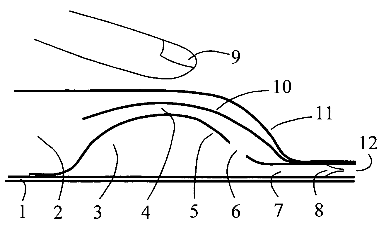
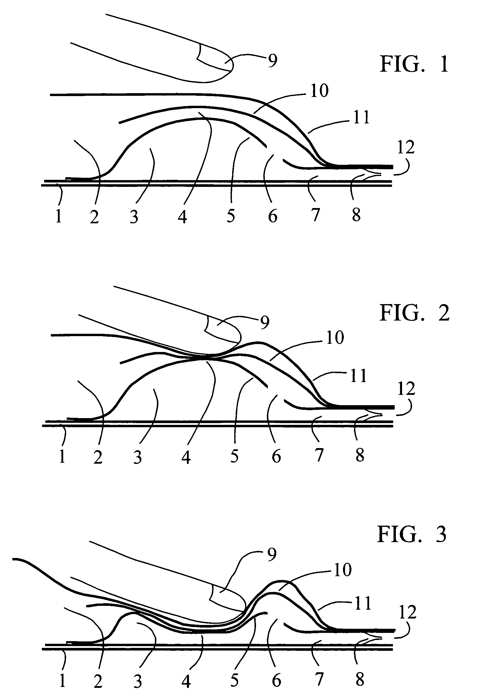
[0024]In FIG. 1 a cut through side view of the pump assembly of a fluid dispenser is illustrated. Comprising elements include a base 1 which is attached by peripheral seal to a fluid reservoir of which a flexible portion of the upper reservoir wall 11 is shown. The reservoir wall 11 fully encloses a fluid material as product contained within the reservoir chamber 2, this fluid is also found in and in fluidic communication with fluid in the channel 4, pump chamber 3, and dispensing channel 7. All fluid is sealed away from the atmosphere so as to exclude fluid product contamination, prevent deterioration, and eliminate quantitative loss. The fluid held within the reservoir 2, channels, and pump chamber 3 has only one outlet to the atmosphere, through a one-way exit valve 8 and out an orifice 12 for dispersal. The valve 8 may consist of any one or more known types including duckbill, check, compression, elastic, flap, reed, spring, and similar one-way mechanisms. All, by their operatio...

example 2

[0030]In FIG. 6 a cut through side view of the pump assembly of a fluid dispenser is illustrated in a fashion similar to FIG. 1. The familiar elements of base 1, reservoir wall 11, pump chamber 3, reservoir chamber 2, dispensing channel 7, orifice 12, channel 4, and pump wall 5 are again shown. Additionally, new features are illustrated which include a channel 4 which is depicted as a pipe whose wall is formed independent of any other pump component and has plural channel inlets formed, in this example, by bifurcated pip extensions defined as a mid pipe 16 and far pipe 17. Each of these pipes terminates in an inlet respectively described as mid inlet 15 and far inlet 18. Various placements of such inlets at diverse locations within the reservoir chamber 2 allows the gathering of fluid product so as to eliminate or greatly reduce irretrievable wastage. Also newly illustrated is a pump element described as a spring 14 which, by its resistive resilient nature, aids in both defining the...


PUM


Abstract

A hand operated fluid dispenser comprised of a sealed flexible reservoir chamber containing a fluid, a channel capable of blockage by finger pressure applied to a specific position, a flexible pump chamber drawing fluid from the reservoir via this channel, and a pump cycled by external finger pressure applied to a layered array of the channel and pump chamber. This class of simple, inexpensive, disposable dispensers is particularly useful in packaging cosmetics, foodstuffs, and healthcare products. As pocketable dispensers they are popular for conveniently dispensing small amounts of stored viscous liquids easily damaged when exposure to the atmosphere, a condition where sealed reservoirs coupled with airless pumps work together successfully preventing product contamination, deterioration and loss.

Description

FIELD OF THE INVENTION[0001]The present invention relates to hand operated fluid dispensers utilizing a sealed flexible reservoir chamber containing a fluid, a flexible pump chamber, and a pump action cycled by application of finger pressure. This class of simple, disposable dispensers is particularly useful in packaging and distributing of cosmetics, foodstuffs, and healthcare products. As pocketable packet dispensers they are popular for conveniently dispensing small amounts of stored fluids and viscous liquids easily damaged when exposed to the atmosphere, a condition where the sealed reservoir coupled with an airless pump work together precluding product contamination, deterioration and loss.BACKGROUND OF THE INVENTION[0002]Dispersal of relatively viscous liquids such as liquid soaps, hand sanitizing fluids, cosmetic creams, insect repellant lotions and similar fluids is often accomplished by either squeezing plastic tubes or bottles with closable caps or pumping fluid from bott...

Claims


Application Information

Patent Timeline
Patent Type & Authority Patents(United States)
IPC IPC(8): B65D37/00
CPCB65D37/00B05B11/3032B05B11/3033B05B11/1033B05B11/1032
Inventor HARPER, WILLIAM A.
Owner HARPER WILLIAM A
Why Eureka
Try Eureka