System for starting internal combustion engine

a technology for internal combustion engines and starting systems, which is applied in the direction of engine starting, machine/engines, electric generator control, etc., to achieve the effect of improving the engine-restarting respons

Active Publication Date: 2013-11-26
DENSO CORP
View PDF18 Cites 11 Cited by
  • Summary
  • Abstract
  • Description
  • Claims
  • Application Information

AI Technical Summary

Benefits of technology

[0023]Specifically, the present invention aims at providing engine starting systems, each of which is designed to improve the engine-restarting response to the occurrence of an engine restart request to thereby meet the more rapid restart requirements.
[0025]The engine starting system according to the one aspect of the present invention is designed to individually adjust the first delay time from the first timing to the second timing when the first timing is responsive to the turning on of the starter switch and the second delay time from the first timing to the second timing when the first timing is responsive to the occurrence of the engine restart request. Thus, it is possible to determine the first delay time appropriately for the turning on of the starter switch, and determine the second delay time appropriately for the occurrence of the engine restart request. This results in improving the engine-restarting response to the occurrence of an engine restart request to thereby meet requirements to more rapidly restart the internal combustion engine after the engine automatic stop task has been applied thereto.
[0027]The configuration of the engine starting system according to the alternative aspect of the present invention makes possible to determine the delay time appropriately for the occurrence of the engine restart request. This results in improving the engine-restarting response to the occurrence of an engine restart request to thereby meet requirements to more rapidly restart the internal combustion engine after the engine automatic stop task has been applied thereto.
[0028]The configuration of the engine starting system according to the alternative aspect of the present invention also makes possible to determine the second delay time appropriately for the measured rotational speed of the first output shaft of the internal combustion engine at the occurrence of an engine restart request.

Problems solved by technology

The inventors have discovered that there are some problems in the conventional starters.

Method used


Image

  • System for starting internal combustion engine
  • System for starting internal combustion engine
  • System for starting internal combustion engine

Examples


first embodiment

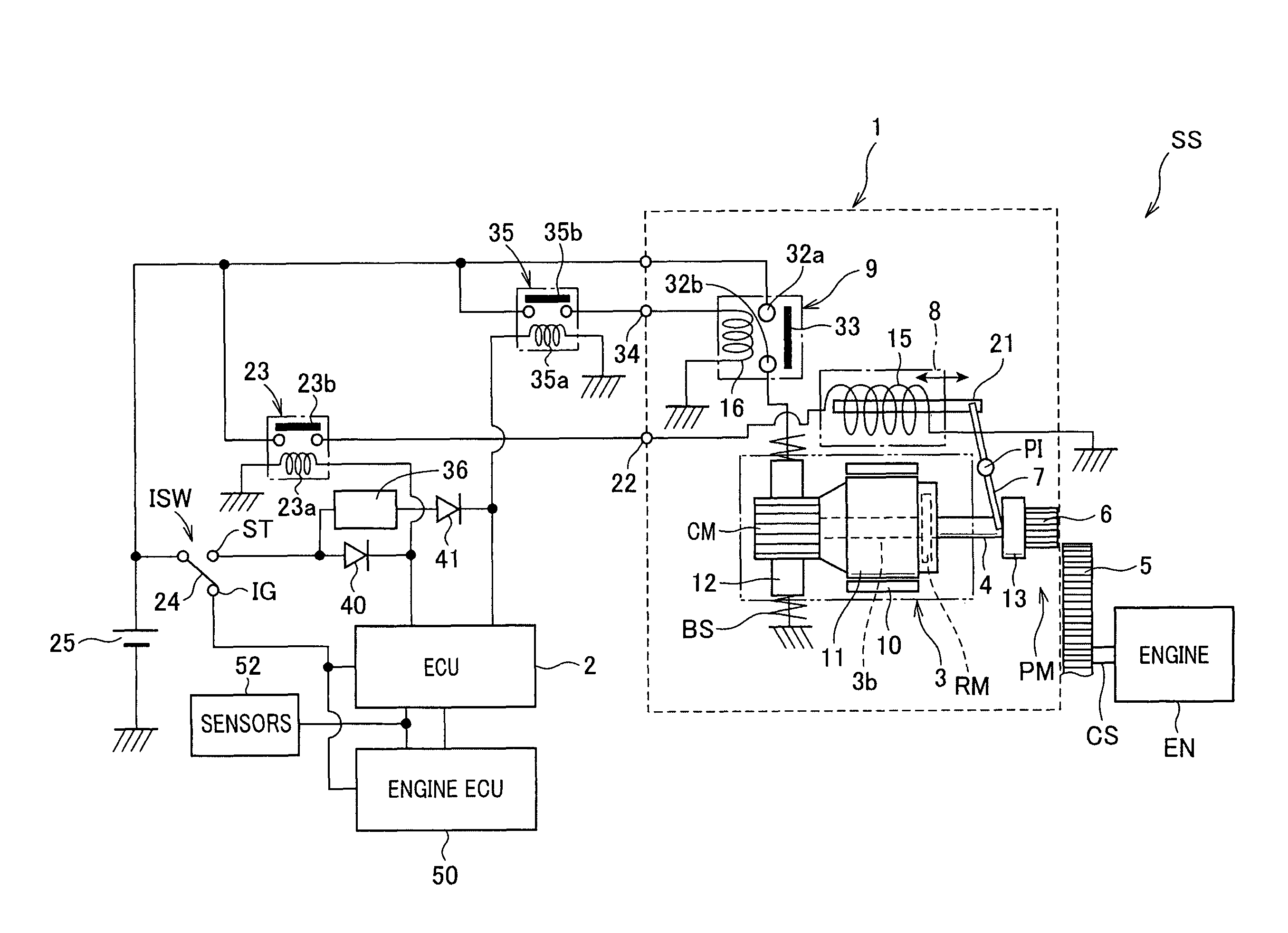
[0043]Referring to FIGS. 1 to 6, an engine starting system SS according to the first embodiment of the present invention is installed in, for example, an engine room of a motor vehicle. The engine starting system SS works as an idle reduction system to automatically stop an internal combustion engine (referred to as “engine”) EN and restart the engine EN.

[0044]The engine starting system SS includes a starter 1 used to start the engine EN, and an electronic control unit (ECU) 2 for control of operations of the starter 1 at the start of the engine EN. The engine starting system SS also includes a first drive relay 23, a battery 25, a second drive relay 35, a delay circuit 36, a first diode 40, and a second diode 41.

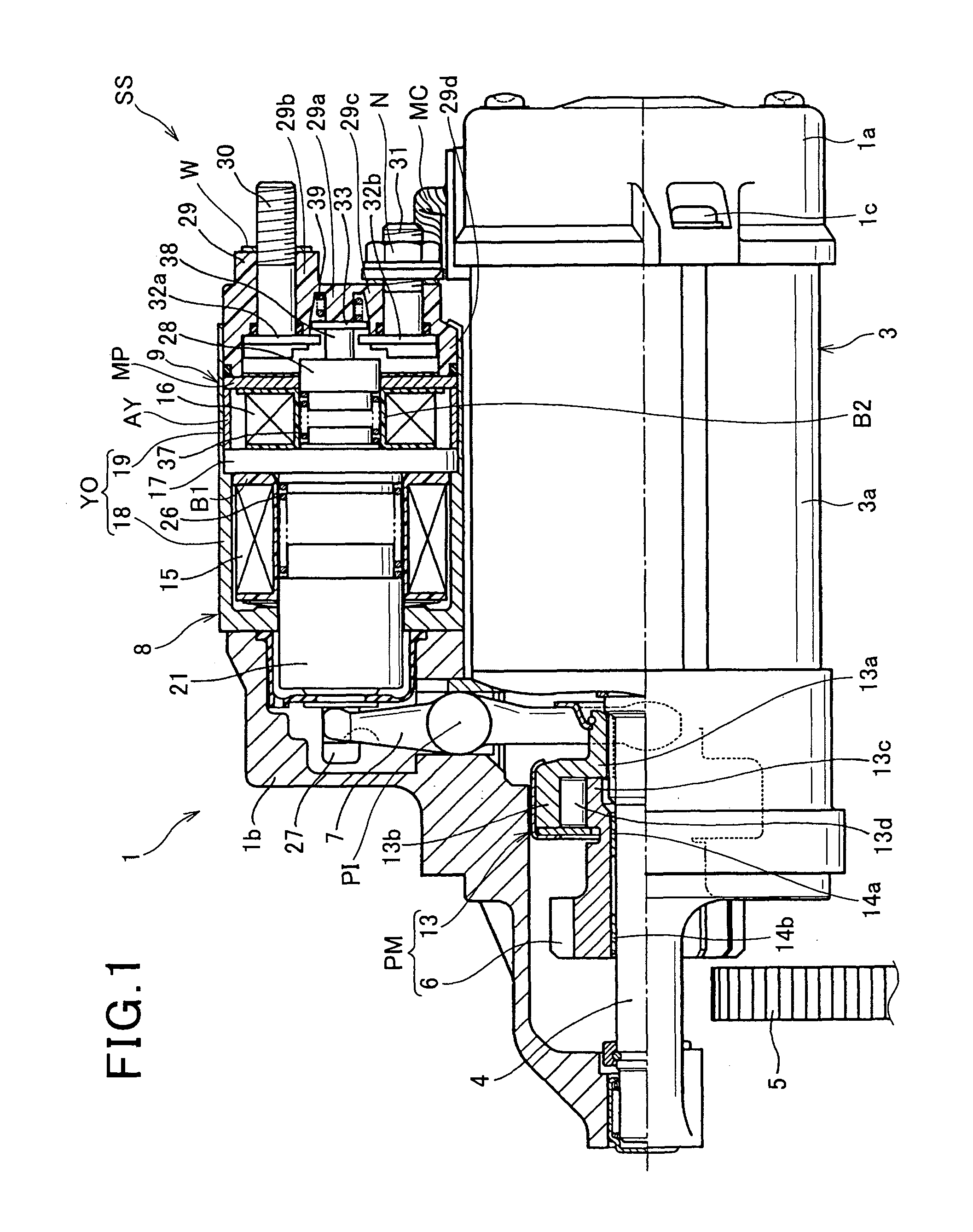
[0045]Referring to FIG. 1, the starter 1 includes a front housing (front frame) 1a, an end housing (end frame) 1b, a motor 3, an output shaft 4, an electromagnetic (solenoid) actuator 8 having a shift lever 7, and a motor-energizing switch 9.

[0046]Referring to FIGS. 1 and 2...

second embodiment

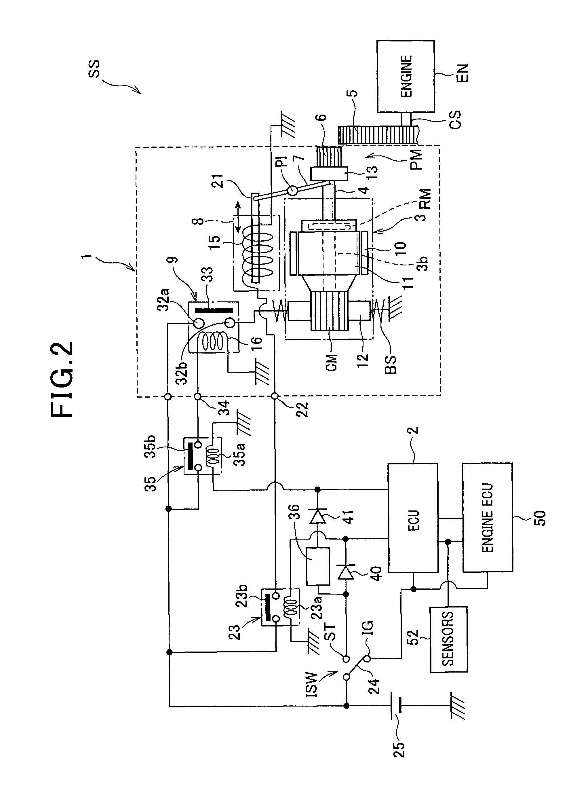
[0169]The engine starting system SS according to the first embodiment is designed such that the solenoid actuator 8 for shifting the movable pinion member PM to the ring gear 5 of the engine EN, and the motor-energizing switch 9 for energizing and deenergizing the motor 3 are combined with each other.

[0170]The present invention is however not limited to the structure of the engine starting system SS according to the first embodiment.

[0171]FIG. 8 represents an engine starting system SS1 according to the second embodiment of the present invention.

[0172]Referring to FIG. 8, the engine starting system SS1 includes a starter 1A, an ECU 2, a drive relay 35, a battery 25, and a delay circuit 70.

[0173]In comparison to the structure of the starter 1, the starter 1A is comprised of a solenoid switch 60 in place of the solenoid actuator 8 and the motor-energizing switch 9; this solenoid switch 60 serves as the solenoid actuator 8 and the motor-energizing switch 9.

[0174]The solenoid switch 60 i...


PUM


Abstract

In an engine starting system, when a first solenoid is energized at a first timing in response to any one of a turning on of a starter switch and an occurrence of an engine restart request, a solenoid actuator shifts a pinion to a ring gear to be engaged with the ring gear. When a second solenoid is energized, a solenoid switch member energizes a motor. A determiner determines a second timing of energization of the second solenoid after the first timing so that a first delay time from the first timing to the second timing when the first timing is responsive to the turning on of the starter switch is different from a second delay time from the first timing to the second timing when the first timing is responsive to the occurrence of the engine restart request.

Description

CROSS REFERENCE TO RELATED APPLICATIONS[0001]This application is based on Japanese Patent Applications 2009-114626 and 2010-028311 filed on May 11, 2009 and Feb. 11, 2010, respectively. This application claims the benefit of priority from the Japanese Patent Applications, so that the descriptions of which are all incorporated herein by reference.FIELD OF THE INVENTION[0002]The present invention relates to engine starting systems for starting internal combustion engines. More particularly, the present invention relates to such engine starting systems designed to restart internal combustion engines when an engine restart request occurs after an engine automatic stop task has been applied to the internal combustion engines.BACKGROUND OF THE INVENTION[0003]One of conventional effective CO2 reduction measures in global warning countermeasures is to install idle reduction systems into motor vehicles. Such an idle reduction system installed in a motor vehicle is designed to shut off fuel i...

Claims


Application Information

Patent Timeline
Patent Type & Authority Patents(United States)
IPC IPC(8): F02N11/00F02N15/02H02P9/04F02N11/08
CPCF02N11/0844F02N11/0855F02N15/067F02N2300/2011Y02T10/48Y02T10/40
Inventor NOTANI, HIDEYASENDA, TAKASHI
Owner DENSO CORP
Why Eureka
Try Eureka