Multiport amplifier and wireless device using the same

a wireless device and amplifier technology, applied in amplifiers, amplifiers with semiconductor devices/discharge tubes, amplifiers, etc., can solve the problem that the signal of a small amplitude cannot be received with a high degree of accuracy, and achieve the effect of improving the quality of communication

Active Publication Date: 2013-12-31
MITSUBISHI ELECTRIC CORP
View PDF19 Cites 7 Cited by
  • Summary
  • Abstract
  • Description
  • Claims
  • Application Information

AI Technical Summary

Benefits of technology

[0011]According to the present invention, an amplitude difference and a phase difference among output signals from individual amplifiers can be reduced to remove unnecessary frequency components included in each of the output signals, whereby isolation between output terminals can be improved, thus making it possible to enhance the quality of communication.

Problems solved by technology

However, if the multiport amplifier is constructed as shown in FIG. 15 and FIG. 16, there will be a possibility that a signal of a small amplitude can not be received with a high degree of accuracy due to the limitation of the dynamic range of the reception sensitivity of circuits (RF reception units 391, 397) which receive the composite signals.

Method used


Image

  • Multiport amplifier and wireless device using the same
  • Multiport amplifier and wireless device using the same
  • Multiport amplifier and wireless device using the same

Examples


first embodiment

[0028]Hereinafter, preferred embodiments of the present invention will be explained while referring to the accompanying drawings.

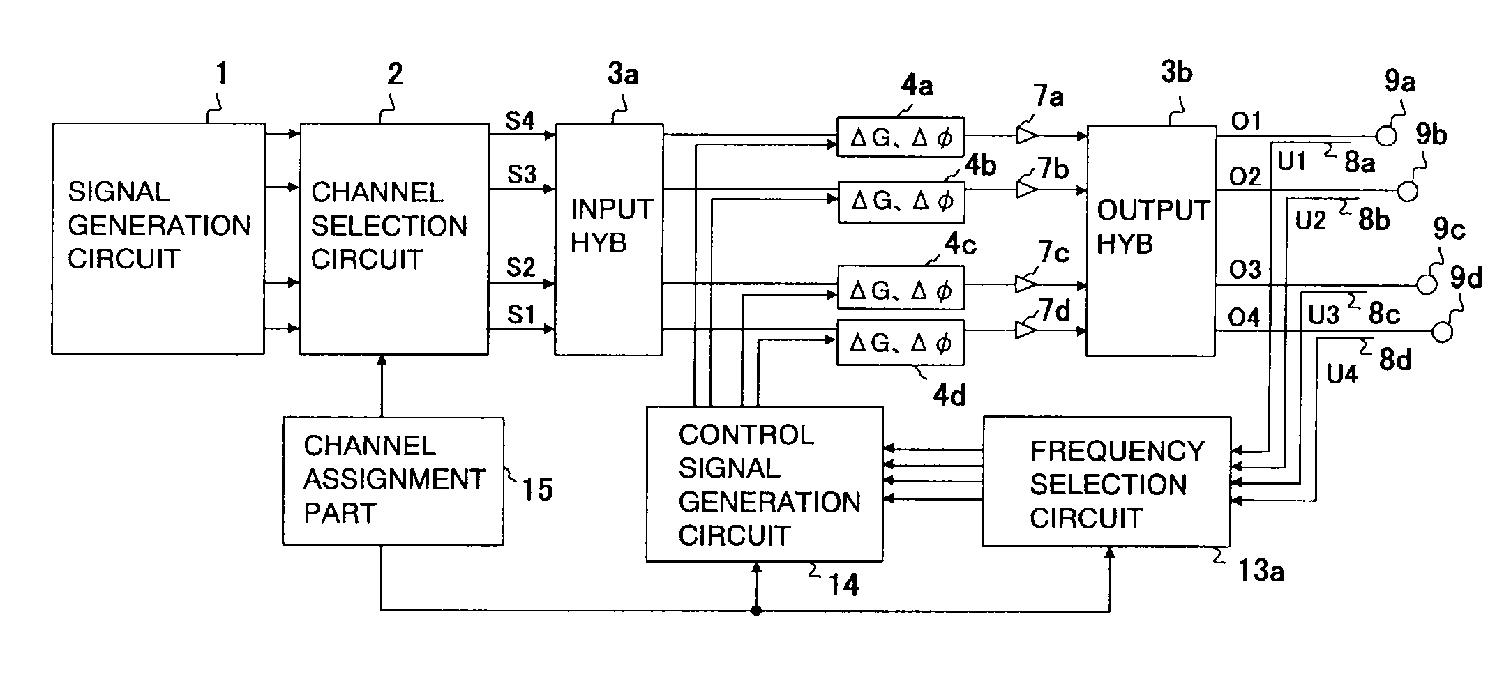
[0029]FIG. 1 is a block diagram showing the arrangement of a multiport amplifier according to a first embodiment of the present invention, wherein an example of the multiport amplifier having an error compensation circuit with the number of ports being four is shown.

[0030]In FIG. 1, the multiport amplifier is provided with a signal generation circuit 1, a channel selection circuit 2, an input hybrid (input HYB) 3a, an output hybrid (output HYB) 3b, gain and phase control circuits (ΔG, Δφ) 4a through 4d, amplifiers 7a through 7d, output coupling circuits 8a through 8d, output terminals 9a through 9d, a frequency selection circuit 13a, a control signal generation circuit 14, and a channel assignment part 15, wherein it is constructed such that the plurality of amplifiers 7a through 7d are combined in parallel with one another.

[0031]A plurality of (here, “4 c...

second embodiment

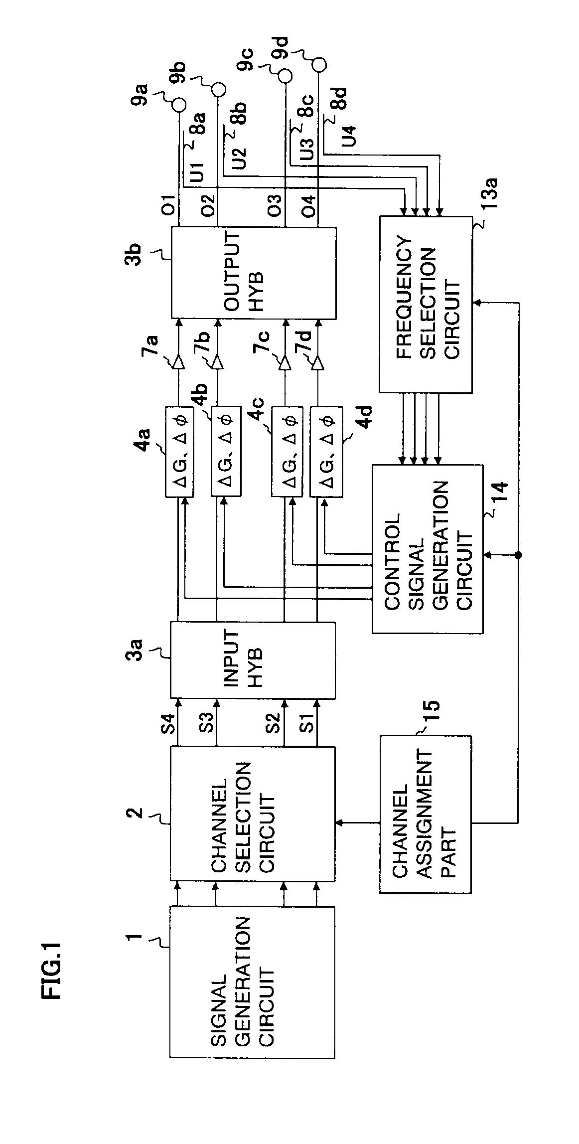
[0068]Here, note that in the above-mentioned first embodiment (FIG. 1 and FIG. 2), the input hybrid 3a composed of an analog circuit is used, but an input hybrid 3Da composed of a digital circuit may be used, as shown in FIG. 3.

[0069]FIG. 3 is a block diagram showing a multiport amplifier according to a second embodiment of the present invention, wherein an arrangement thereof having an error compensation circuit with the number of ports being four is shown.

[0070]In FIG. 3, those components which are similar to the above-mentioned ones (see FIG. 1) are denoted by the same reference numerals and characters as those in the above-mentioned embodiment, or with “D” being attached to reference numerals, and a detailed description thereof is omitted.

[0071]In this case, the input hybrid 3Da is constituted by a digital circuit. In addition, a signal generation circuit 1D and a channel selection circuit 2D are also composed of digital circuits, respectively.

[0072]The signal generation circuit...

third embodiment

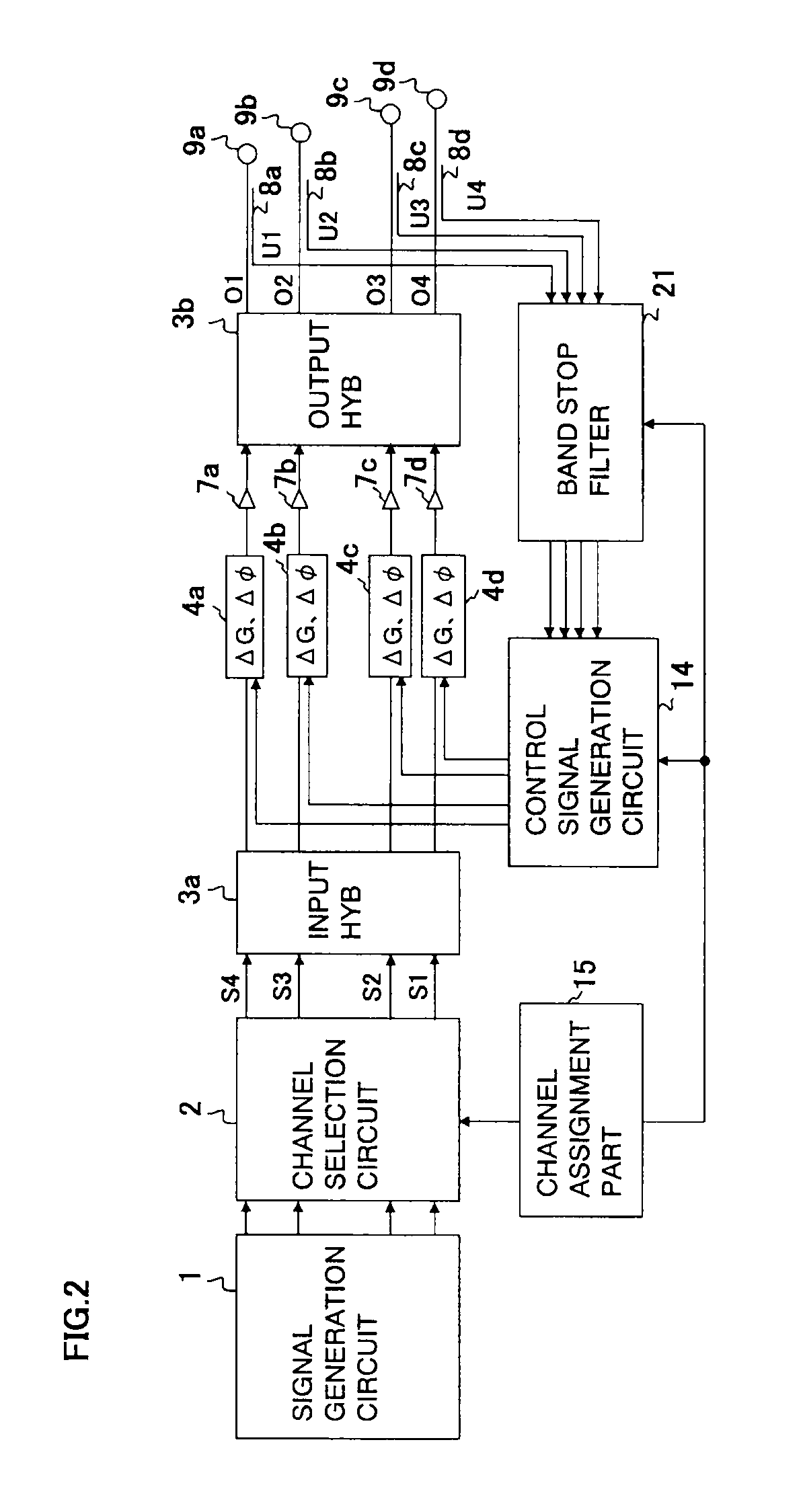
[0079]Here, note that in the above-mentioned second embodiment (FIG. 3), only the input hybrid 3Da is composed of the digital circuit, but at least one of the input hybrid and the plurality of gain and phase control circuits can be composed of a digital circuit, and as shown in FIG. 4, not only the input hybrid 3Da but the gain and phase control circuits 4Da through 4Dd may be composed of digital circuits, respectively.

[0080]FIG. 4 is a block diagram showing a multiport amplifier according to a third embodiment of the present invention, wherein an arrangement thereof having an error compensation circuit with the number of ports being four is shown.

[0081]In FIG. 4, those components which are similar to the above-mentioned ones (see FIG. 3) are denoted by the same reference numerals and characters as those in the above-mentioned embodiment, or with “D” being attached to reference numerals, and a detailed description thereof is omitted.

[0082]In this case, not only the input hybrid 3Da ...


PUM


Abstract

A multiport amplifier and a wireless device using the same are obtained in which isolation among output terminals is improved, whereby the quality of communication is improved. The multiport amplifier includes an input hybrid, an output hybrid, a plurality of amplifiers and a plurality of gain and phase control circuits that are inserted between the input hybrid and the output hybrid, a plurality of output coupling circuits that are inserted between the output hybrid and a plurality of output terminals so that they receive output extraction signals corresponding to a plurality of output signals, and a feedback circuit including a frequency selection circuit that is inserted between the plurality of output coupling circuits and the plurality of gain and phase control circuits.

Description

TECHNICAL FIELD[0001]The present invention relates to a multiport amplifier having an error compensation circuit, and to a wireless device using the same.BACKGROUND ART[0002]A multiport amplifier is provided with an input hybrid, an output hybrid, and a plurality of amplifiers connected between them, wherein input signals having different frequency components are inputted to a plurality of input terminals of the input hybrid, and are distributed, amplified and combined, and output signals having frequency components different from those of the above-mentioned input signals are outputted from a plurality of output terminals of the output hybrid. As a result of this, the individual amplifiers are of an arrangement to amplify all the different frequency components, and hence, it is possible to decrease the deterioration of communication quality at the time of the failure of the amplifiers, as compared with an arrangement in which an amplifier is provided for each of the frequency compo...

Claims


Application Information

Patent Timeline
Patent Type & Authority Patents(United States)
IPC IPC(8): H03F3/68
CPCH03F3/602H03F3/24H03F2200/204H03F3/68
Inventor HANGAI, MASATAKEMORI, KAZUTOMITAJIMA, KENICHITAHARA, YUKIHIROHIEDA, MORISHIGE
Owner MITSUBISHI ELECTRIC CORP
Why Eureka
Try Eureka