Managing a spinlock indicative of exclusive access to a system resource

a system resource and spinlock technology, applied in the field of multiprocessor computing systems, can solve the problems of inefficient cache synchronization between two or more processors, inefficient spinlock mechanism with respect to power consumption, and inability to so as to efficiently synchronize operations and efficiently utilize power and system resources.

Active Publication Date: 2014-04-29
NVIDIA CORP
View PDF21 Cites 3 Cited by
  • Summary
  • Abstract
  • Description
  • Claims
  • Application Information

AI Technical Summary

Benefits of technology

[0011]One advantage of the disclosed technique is that two or more processor cores may efficiently synchronize operations using a low-latency spinlock construct while efficiently utilizing power and system resources.

Problems solved by technology

However, the spinlock mechanism can be very inefficient with respect to power consumption.
The acquire function can be tremendously inefficient because it causes the processor to execute the same code repeatedly in a loop, causing cache synchronization among the two or more processors.
Each of these operations is power inefficient and cause excessive power consumption.
Additionally, the processor executing the acquire function is also required to maintain cache synchronization for each other processor of the two or more processors that is testing this variable in such a manner that the acquire function consumes additional cache line space as well as requiring intra-processor or inter-processor synchronization on related cache lines.
The acquire function executing on one processor not only increases power consumption for that processor but also increases power consumption for one or more additional processors, leading to yet greater net power consumption.
The significant processing burden associated with the spinlock acquire function can lead to poor overall power efficiency in multi-processor systems.

Method used


Image

  • Managing a spinlock indicative of exclusive access to a system resource
  • Managing a spinlock indicative of exclusive access to a system resource
  • Managing a spinlock indicative of exclusive access to a system resource

Examples


Embodiment Construction

[0017]In the following description, numerous specific details are set forth to provide a more thorough understanding of the present invention. However, it will be apparent to one of skill in the art that the present invention may be practiced without one or more of these specific details. In other instances, well-known features have not been described in order to avoid obscuring the present invention.

System Overview

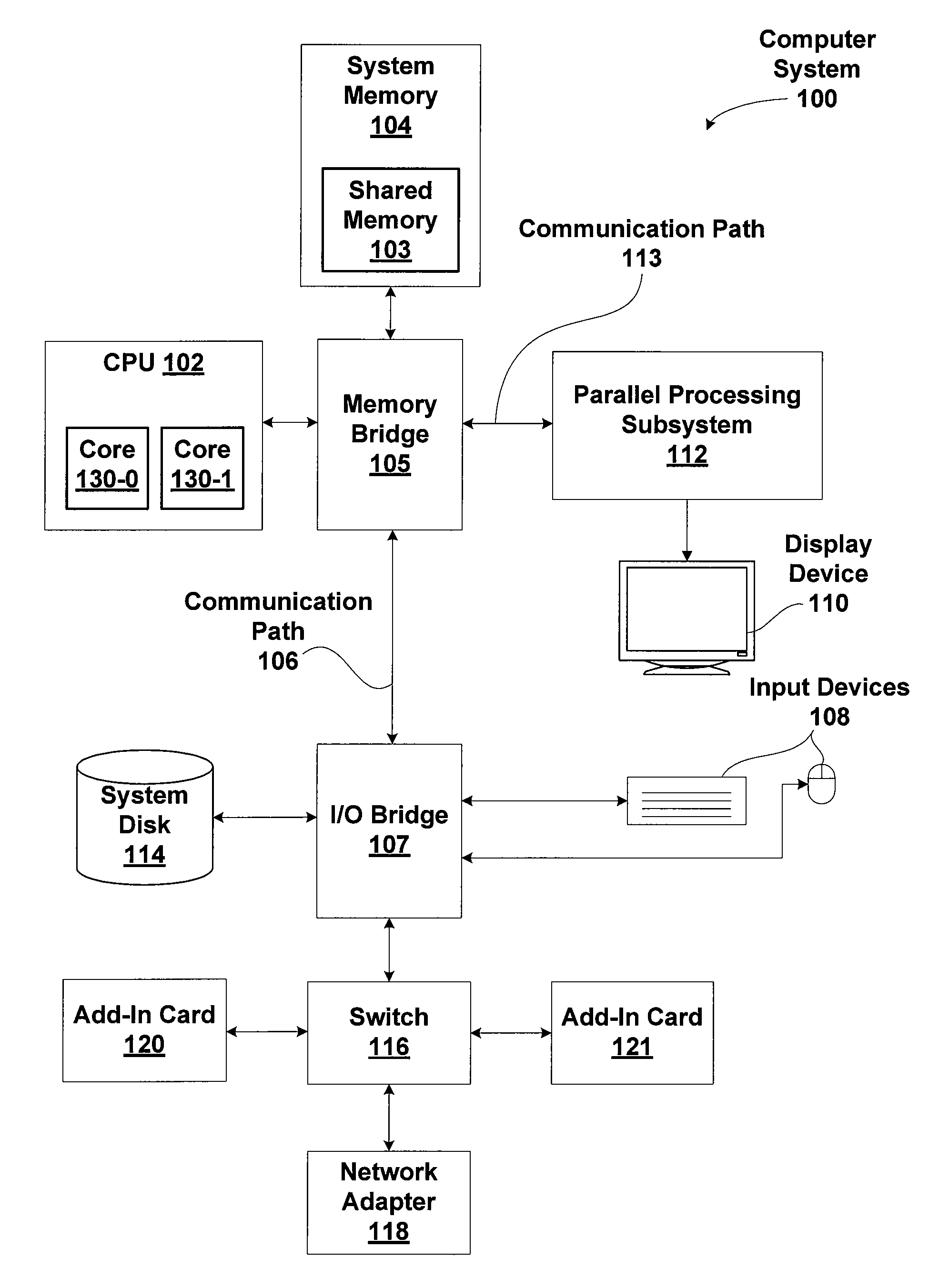
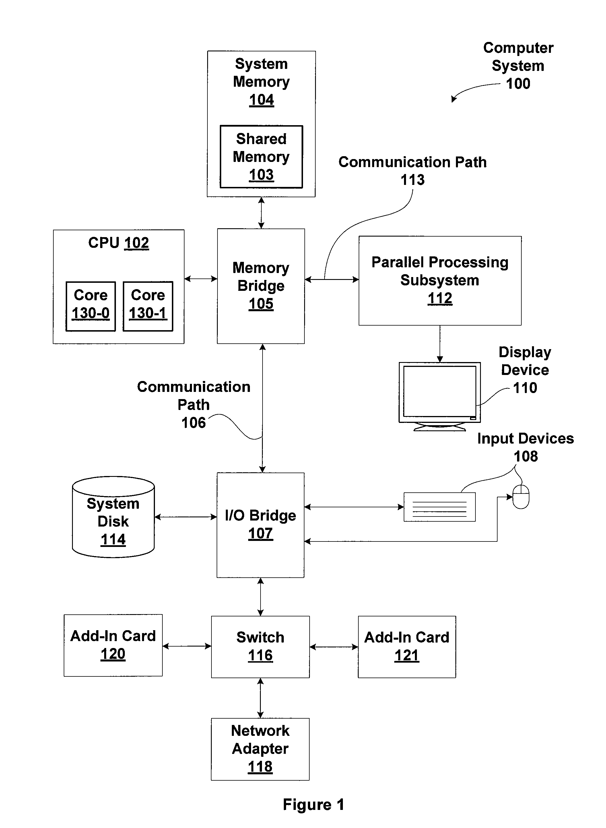
[0018]FIG. 1 is a block diagram illustrating a computer system 100 configured to implement one or more aspects of the present invention. Computer system 100 includes a central processing unit (CPU) 102 and a system memory 104 communicating via an interconnection path that may include a memory bridge 105. Memory bridge 105, which may be, e.g., a Northbridge chip, is connected via a bus or other communication path 106 (e.g., a HyperTransport link) to an I / O (input / output) bridge 107. I / O bridge 107, which may be, e.g., a Southbridge chip, receives user input from one or mor...


PUM


Abstract

One embodiment of the present invention sets forth a technique for synchronization between two or more processors. The technique implements a spinlock acquire function and a spinlock release function. A processor executing the spinlock acquire function advantageously operates in a low power state while waiting for an opportunity to acquire spinlock. The spinlock acquire function configures a memory monitor to wake up the processor when spinlock is released by a different processor. The spinlock release function releases spinlock by clearing a lock variable and may clear a wait variable.

Description

BACKGROUND OF THE INVENTION[0001]1. Field of the Invention[0002]The present invention generally relates to multi-processor computing systems and more specifically to a method for power optimized multi-processor synchronization.[0003]2. Description of the Related Art[0004]Multi-processor systems conventionally include two or more processors implemented on one or more integrated circuit. The two or more processors are typically configured to independently execute programming instructions. Certain applications require that the two or more processors synchronize operations at specific points in execution, for example to share system resources.[0005]One technique for synchronizing operations between the two or more processors involves a programming construct known as a spinlock. The spinlock is a blocking mechanism that enables one processor at a time to own a lock and have exclusive access to system resources corresponding to the lock. The spinlock mechanism beneficially provides signif...

Claims


Application Information

Patent Timeline
Patent Type & Authority Patents(United States)
IPC IPC(8): G06F12/00
CPCG06F9/52G06F1/3206G06F1/3225G06F1/3228G06F9/4405
Inventor OVERBY, MARK A.CURRID, ANDREW
Owner NVIDIA CORP
Why Eureka
Try Eureka