

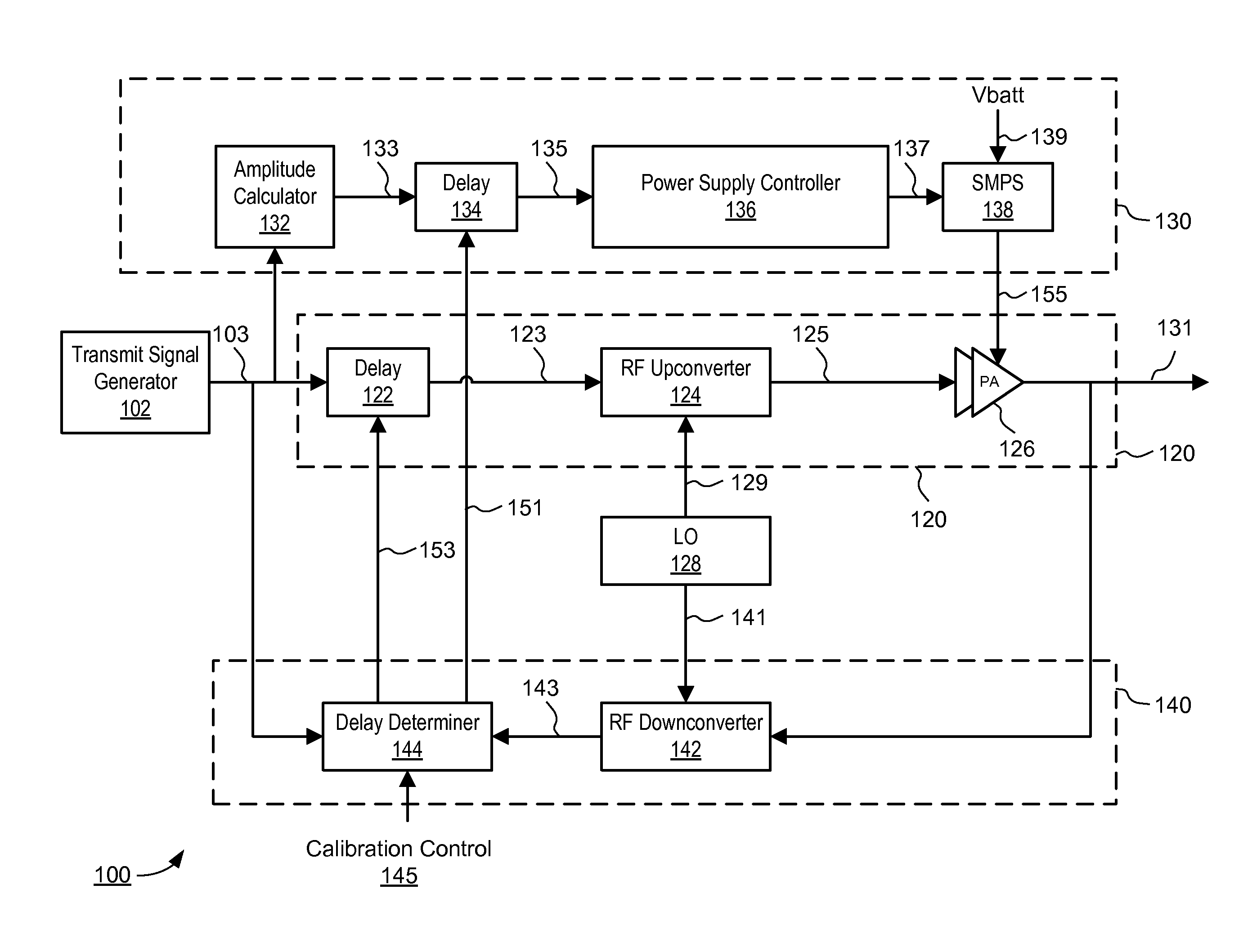
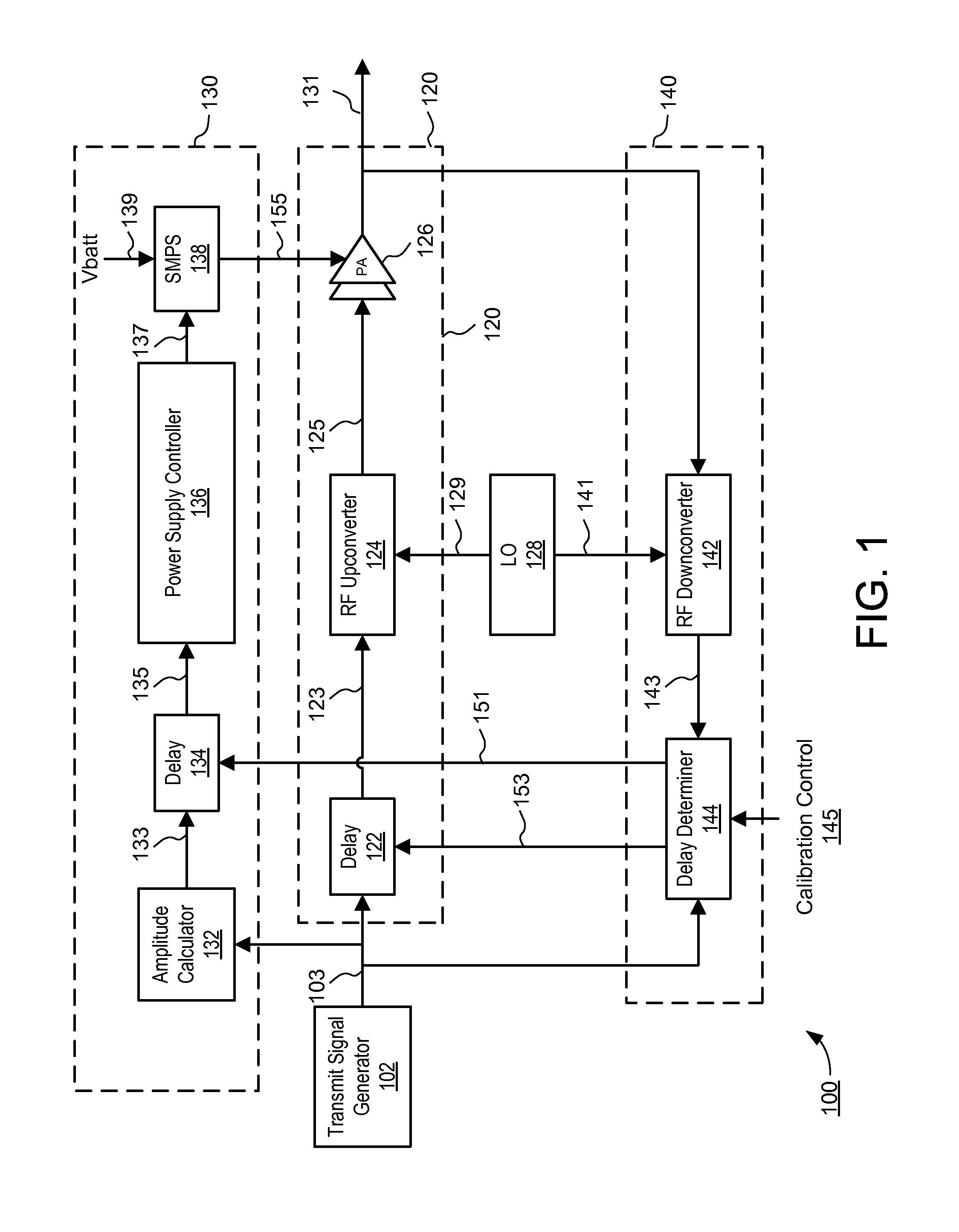
Envelope tracking power amplifier system with delay calibration
a technology of delay calibration and power amplifier, which is applied in the direction of secret communication, digital transmission, system details of baseband, etc., can solve the problems of distortion of output signal, unfavorable misalignment, and inability to adjust the delay
- Summary
- Abstract
- Description
- Claims
- Application Information
AI Technical Summary
Benefits of technology
Problems solved by technology
Method used
Image

Examples
Embodiment Construction
[0021]The Figures (FIG.) and the following description relate to various embodiments by way of illustration only. It should be noted that from the following discussion, alternative embodiments of the structures and methods disclosed herein will be readily recognized as viable alternatives that may be employed without departing from the principles discussed herein.
[0022]Reference will now be made in detail to several embodiments, examples of which are illustrated in the accompanying figures. It is noted that wherever practicable similar or like reference numbers may be used in the figures and may indicate similar or like functionality. The figures depict various embodiments for purposes of illustration only. One skilled in the art will readily recognize from the following description that alternative embodiments of the structures and methods illustrated herein may be employed without departing from the principles described herein.
[0023]An envelope tracking power amplifier system time...
PUM
 Abstract
Description
Claims
Application Information