Backlight module

a backlight module and backlight technology, applied in the field of manufacturing, can solve the problems of long light mixing distance, inability to meet the needs of light weight and compactness at the same time, and the backlight design of the led backlight module in the traditional technology cannot meet the needs of light weight and compactness

Active Publication Date: 2014-09-16
TCL CHINA STAR OPTOELECTRONICS TECH CO LTD
View PDF12 Cites 4 Cited by
  • Summary
  • Abstract
  • Description
  • Claims
  • Application Information

AI Technical Summary

Benefits of technology

[0013]As a possible technical solution, a light output surface of the light diffusion / guide strip has a plurality of light diffusion particles, and at least one surface of the light diffusion / guide strip is frosted or coated with nano-material for enhancing the diffusion efficiency.
[0018]The advantages of the present invention are that a cross section of a bottom of the light guide plate is designed to be a shape of isosceles triangle, and two sides of the shape of isosceles triangle are disposed with the light emitting assemblies. In comparison with a side-light type backlight module in a traditional technology, the light emitting assemblies are directly mounted on the back plate, so as to save a heat-dissipation aluminum extrusion member. Thus, the weight of the light guide plate can be reduced, while the brightness and color of the module become uniform. In comparison with a direct-light type backlight module, the two inclined sides of the shape of isosceles triangle are used to mix light based on the transverse width of the light guide plate, so as to shorten the light mixing distance in a vertical direction and thus reduce the module thickness.
[0019]Furthermore, the surface of the light emitting assemblies can be covered with light diffusion / guide strips to further reduce the module thickness. The function of the light diffusion / guide strips is to diffuse the light emitted from the light emitting assemblies, and thus this function is similar to the function of the light guide plate. In comparison with the light guide plate, the light diffusion / guide strips are directly covered on the openings of the receiving recesses, to tightly cover on the surface of the light emitting assemblies, so that it is helpful to enhance the diffusion efficiency of the light, and thus has better effect than that of the light guide plate for further lowering the thickness of the light guide plate. The light emitting assemblies are installed in the receiving recesses of the back plate, so that it is possible to implement the technical solution of covering the light diffusion / guide strip on the light emitting assemblies.

Problems solved by technology

However, it needs a longer light mixing distance, so that the direct-light type LED backlight module needs a greater thickness.
As described above, the backlight design of the LED backlight modules in the traditional technology can not meet needs of light weight and compactness at the same time.

Method used


Image

  • Backlight module
  • Backlight module
  • Backlight module

Examples


Embodiment Construction

[0029]A backlight module according to a preferred embodiment of the present invention is described more detailed by referring to the following detailed description and the accompanying drawings.

[0030]The objects, features and advantages of the present invention can be best understood by referring to the following detailed description of the preferred embodiments and the accompanying drawings. The specification of the present invention provides different embodiments to describe technical features of different implementation solutions, wherein arrangement of various elements in the embodiments is used to clearly describe the content of the present invention, but the present invention is not limited thereto. Meanwhile, numerals of drawings are partially repeated between different embodiments for simplifying the description, but not for building the relationship between the different embodiments.

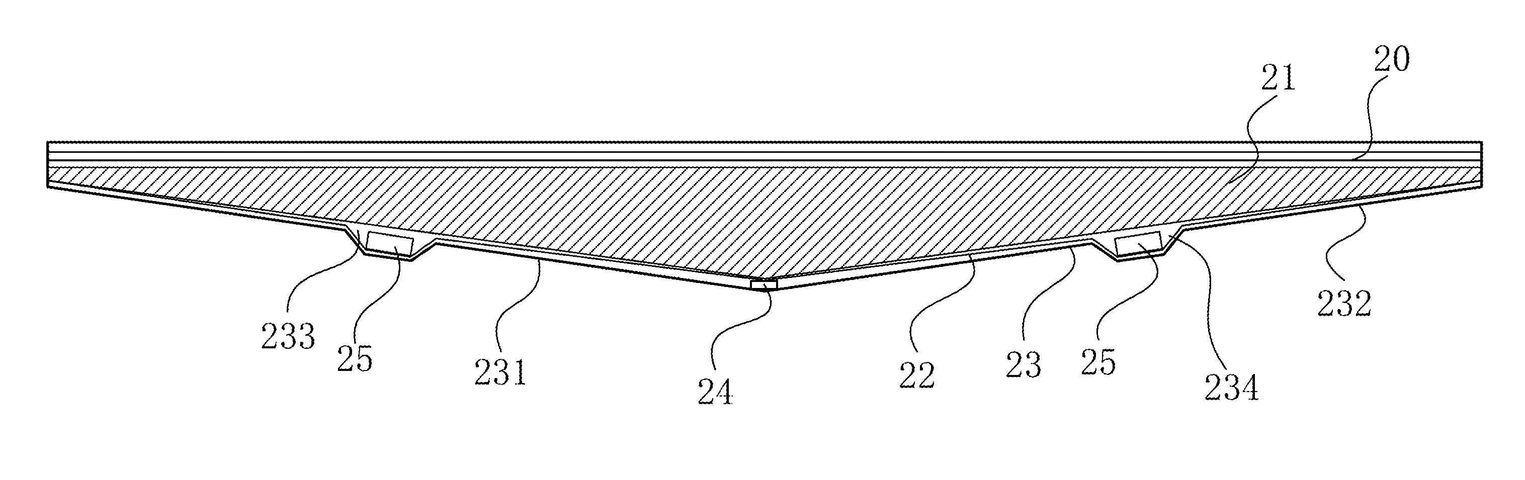
[0031]FIG. 2A is a cross-sectional view of a structure of a backlight module according to a ...


PUM

PropertyMeasurementUnit
shapeaaaaaaaaaa
thermal conductiveaaaaaaaaaa
thermal conductivityaaaaaaaaaa

Abstract

A backlight module has a light guide plate, a back plate and light emitting assemblies. The light guide plate is substantially prism-like. The back plate has a shape corresponding to that of the light guide plate, and has an inclined first side plate and an inclined second side plate opposite to the first side plate. Each of the first and second side plates has at least one receiving recess, and the light emitting assemblies are received in the receiving recesses. In comparison with a side-light type backlight module, the present invention saves a heat-dissipation aluminum extrusion member. In comparison with a direct-light type backlight module, the present invention shortens the light mixing distance in a vertical direction, so as to reduce the module thickness.

Description

FIELD OF THE INVENTION[0001]The present invention relates to a manufacture field of liquid crystal display (LCD), and more particularly to a backlight module.BACKGROUND OF THE INVENTION[0002]In a traditional technology, a light guide plate (LGP) in a side-light type LED (light emitting diode) backlight module is generally rectangular. FIG. 1A and FIG. 1B are schematic views of a structure of a side-light type LED backlight module in a traditional technology, wherein FIG. 1A is a perspective view, and FIG. 1B is a cross-sectional view of FIG. 1A taken along a line A-A. The backlight module comprises a back plate 11, two aluminum extrusion members 12, two driver circuit boards 13, a plurality of LEDs 14 and a light guide plate 15. The light guide plate 15 is disposed on a central portion of the back plate 11, and is a rectangular structure. The driver circuit board 13 is provided with the plurality of LEDs 14, and commonly mounted on two sides of the light guide plate 15 with the LEDs...

Claims


Application Information

Patent Timeline
Patent Type & Authority Patents(United States)
IPC IPC(8): G09F13/04G09F13/08F21V8/00G02F1/1335
CPCG02B6/0068G02B6/0088G02F2001/133607G02F1/133607
Inventor FANG, LINDONGKUO, YICHENG
Owner TCL CHINA STAR OPTOELECTRONICS TECH CO LTD
Why Eureka
Try Eureka