Folding apparatus for transferring a patient

a patient and multi-panel technology, applied in the direction of sleeping rug, transportation and packaging, socks, etc., can solve the problems of insufficient caregiver personnel, limited staff in the facility, and the difficulty of transferring patients between beds and other surfaces, so as to reduce hospital waste and increase cleanliness and organization

Active Publication Date: 2014-11-18
ACE SAFETY GEAR
View PDF8 Cites 15 Cited by
  • Summary
  • Abstract
  • Description
  • Claims
  • Application Information

AI Technical Summary

Benefits of technology

[0012]Accordingly, the present invention overcomes the limitations of the prior art by providing a unique and useful foldable patient transfer apparatus with articulating sections that makes it easy to move a person or other heavy object between two surfaces that need not be completely flat or at the same height.

Problems solved by technology

However, it is still very common to encounter situations where there are an insufficient number of caregiver personnel to affect a safe transfer, both for the patient and / or the caregivers.
Many medical facilities have limited staff, ambulance crews may only have two rescuers, and home healthcare aids may be completely on their own yet still must move patients despite the difficulties and risks.
Transferring patients between beds and other surfaces is a significant cause of musculoskeletal injury among caregivers.
Despite the numerous devices that exist to facilitate these transfers, many caregivers still resort to simply physically lifting the patient between the surfaces because of cost, convenience, or lack of training.
Back and shoulder injuries to the healthcare providers occur because the patient transfer causes the caregiver to become off balance and twist their own body in order to move the patient.
In addition, many patients cannot move under their own power or are obese which further increases the risk of injury to the caregivers.
The cost of these injuries to caregivers is significant, but may also create additional patients that now may require transfer themselves.
In addition to the injuries to caregivers, there is a risk of injury or additional pain to the patient from the jerking movements that are common during patient transfers.
If a patient has a broken bone or other injuries, any disruptive movement can complicate the injury or recovery.
The transfer process may cause new injuries such as skin tears, abrasions, friction burns, and joint injury.
Also, intravenous lines, feeding tubes or other monitoring wires often become dislodged or damaged during many patient transfers.
In addition, most of the existing transfer devices are only designed for sliding a patient between two supporting surfaces and cannot hold a patient's weight by themselves which limits usefulness.
These types of devices may or may not work well in these limited situations, however these devices do not address many other common scenarios such as where a patient must be lifted in addition to being transferred, the patient or the surface is not completely flat, or the number or physical ability of the caregivers to affect a safe patient transfer is limited.
While some existing devices are somewhat flexible, most still do not conform very well to a non-supine body.
They can over flex causing a patient to slide off of the board prematurely.
Another problem is that they require a storage space that is the same size as the device.
Unfortunately, the lack of rigidity in the sheet, lack of grasping handles, and the potential for the sheet to rip or tear can lead to the same problems that exist with other current transfer devices.
However, this invention would not permit the safe transfer of a patient that was not in a supine position.
The device is flexible to allow for slightly elevating a patient's head or legs, but the entire device could slope creating an uncomfortable surface on which the patient could accidently slide or fall off.
Also, the flexed device would not allow for proper support of a patient with bent knees without additional padding such as pillows, and would not flex nearly enough to move a patient safely from or to a seated or upright position such as sitting up in bed.
In addition, the device is specifically designed not to bear a patient's weight further limiting its usefulness, for example, if a patient needs to be moved off of a floor to a bed.
While this may allow movement between a semi-reclined surface and a flat surface, it does not permit support of a patient with bent knees or other positions with more than a single bend only in the middle of the device.
Another problem that this device does not solve is the patient that needs to be first lifted off of one surface before transfer between other surfaces of equal height.
However, this device is substantially smaller than a human body and requires multiple devices to affect the transfer.
In addition, use is complicated in that more than one device must be placed all of the way under a patient and then the patient is strapped in place.
Additionally, as the device is less than one half of the size of a body, it may not be used to lift a patient at all.

Method used


Image

  • Folding apparatus for transferring a patient
  • Folding apparatus for transferring a patient
  • Folding apparatus for transferring a patient

Examples


embodiment 100

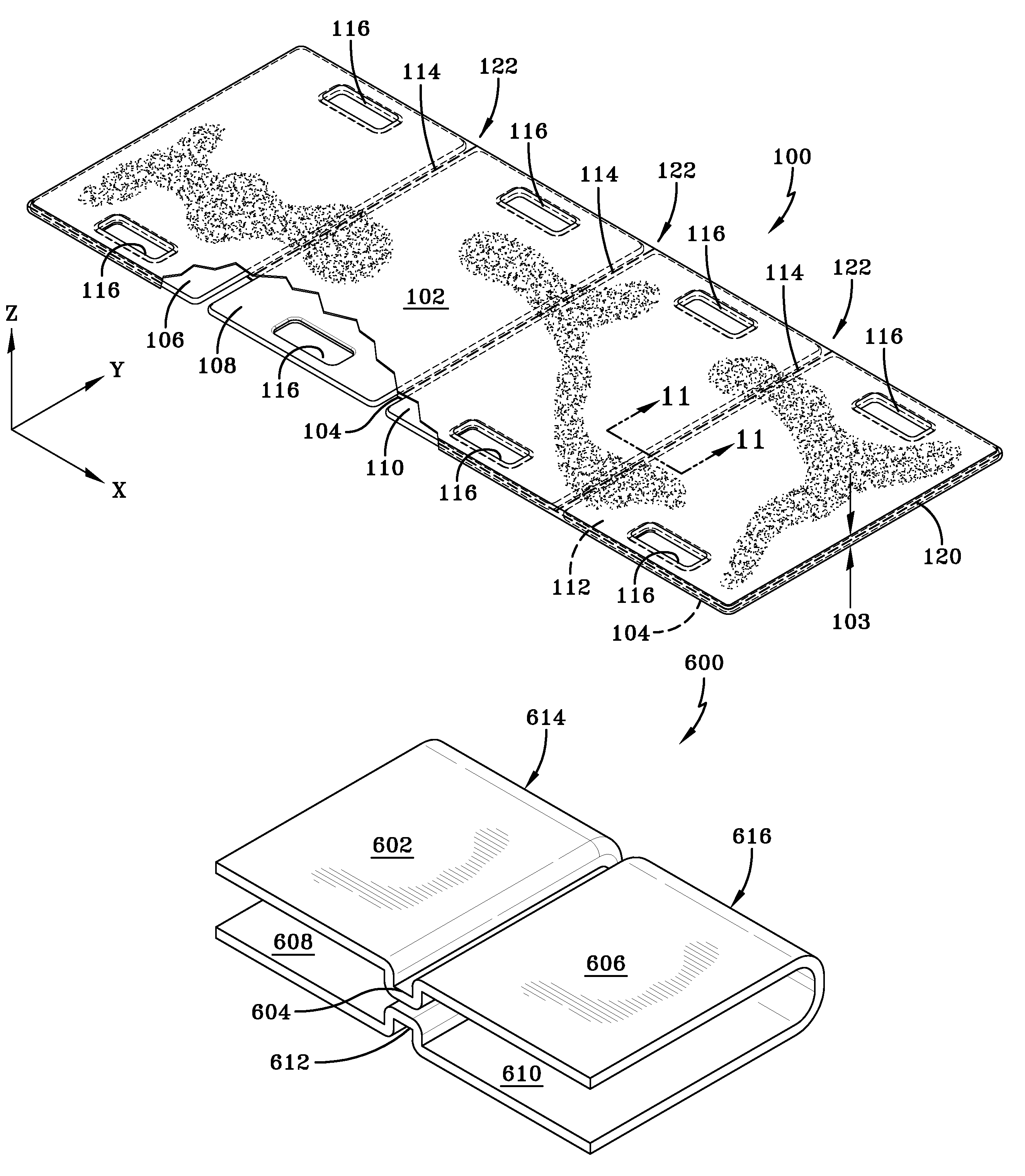
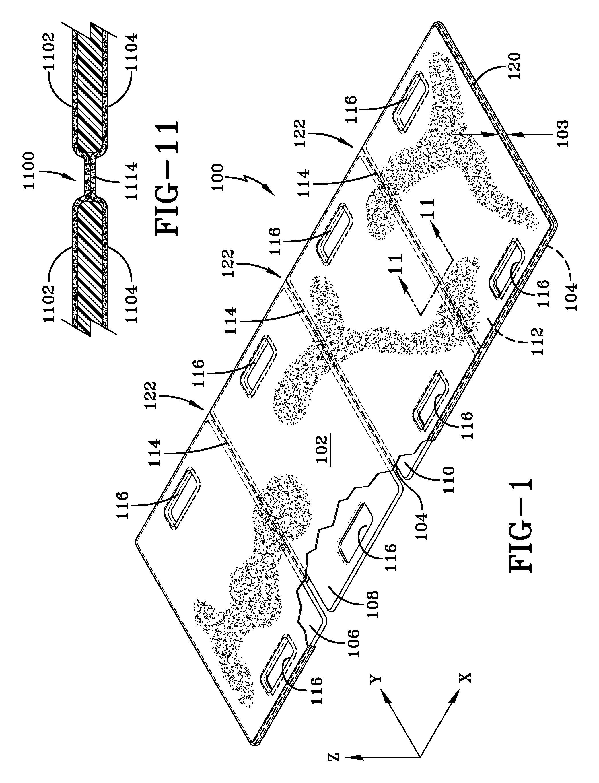
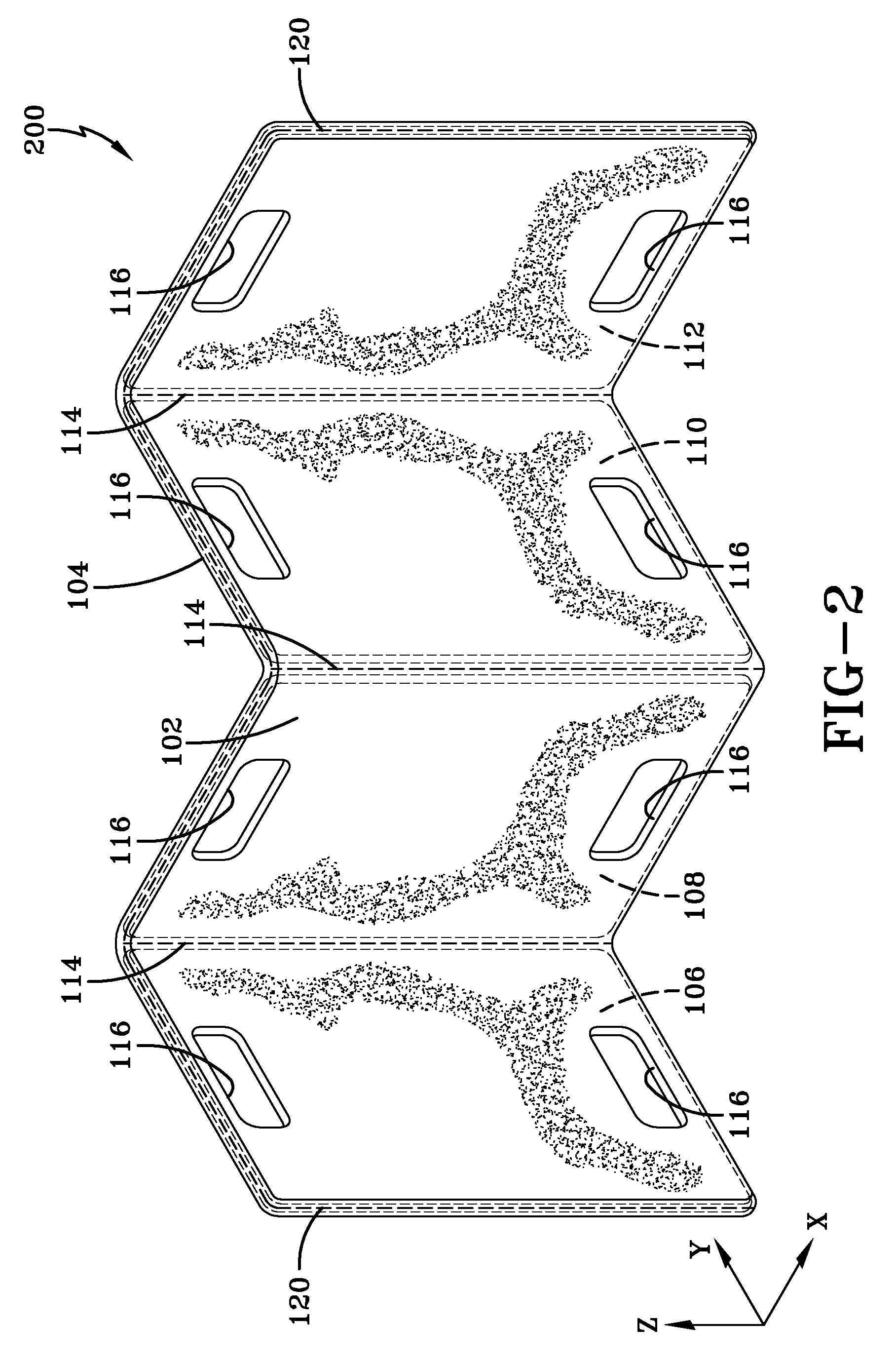
[0059]The patient transfer apparatus 100 may be manufactured in parts for later combination. Each of the rigid inserts 106, 108, 110 and 112 for example may be cut individually from a piece of stock material into the proper size. The rigid inserts 106,108 may then be positioned on top of the bottom layer 104 after an adhesive is optionally placed on each side of the rigid inserts 106, 108, 110 and 112. The material top layer 102 and bottom layer 104 can be joined together at an outside edge of the inserts 106, 110 that are furthest apart with widthwise perimeter seams 120 and the inserts can be captured in the direction of the y axis with lengthwise perimeter seams 122. The hand hold openings 116 can be manufactured utilizing techniques known by one of skill in the art. The hand hold openings 116 can be cut or die stamped, for example through the inserts 106, 108,110 and 112 and layers 102 and 104 cut out and sealed utilizing techniques mentioned previously. In this embodiment 100, ...

embodiment 400

[0068]Next, a plurality of patient straps 422 may extend from the sides of the patient transfer apparatus 400 in a similar manner to the pull strap 418 and the storage straps 420. The patient straps may attach to or extend from any position along the perimeter of the patient transfer apparatus 400 such as extending from a hinge 414 or from the corners for example. The patient straps 422 may be used to secure a patient to the patient transfer apparatus 400 in a horizontal or crisscross fashion. However, the patient straps 422 may also be completely detachable from the patient transfer apparatus 400 so as to not interfere with the ability slide a patient between surfaces. For example, the patient straps 422 may attach to a plurality of handhold openings 416 by using devices comprising clips or by allowing the patient strap 422 to loop through themselves after penetrating the handhold openings 416. The embodiment 400 illustrates four straps; however two, three or more than four straps ...


PUM


Abstract

The invention involves a folding patient transfer apparatus with a material top layer and a material bottom layer. A plurality of inserts has handhold openings that are formed in the inserts that are positioned between the material top layer and the material bottom layer utilizing a sewn plurality of insert seams. The seams form enclosed material chambers containing the inserts. The materials can be disposed of due to contamination; however the inserts can be sterilized reducing hospital waste and cost. The apparatus is configured to slide and / or lift and / or carry a patient from a non-planer surface to a second planer or non-planer surface.

Description

FIELD OF THE INVENTION[0001]The invention relates generally to an apparatus for easily and safely transferring a patient from one surface to another and more specifically to a folding multi-panel patient transfer apparatus, where the apparatus is assembled, designed, manufactured and assembled with multiple panels and fabric hinges.BACKGROUND OF THE INVENTION[0002]The present invention relates to an articulating patient transfer apparatus and method for using same, for transferring a person from one surface to another surface whether both surfaces are relatively flat / planar or not. Although the prior art teaches many devices to aid in moving a person between two different flat surfaces of equal height, such as between a bed and a medical examination table, all of these teachings demonstrate limitations that the present invention addresses and overcomes.[0003]The need to transfer a patient, person or animal that is unable to move completely under its own power is a common occurrence ...

Claims


Application Information

Patent Timeline
Patent Type & Authority Patents(United States)
IPC IPC(8): A61G7/10A61G1/003
CPCA61G7/1074A61G7/1026
Inventor DAVIS, JR., CALVIN, PAUL
Owner ACE SAFETY GEAR
Why Eureka
Try Eureka