Method and device for determining the relative humidity of an insulating liquid filled electric apparatus

a technology of insulating liquid and electric apparatus, which is applied in the direction of transformer/inductance cooling, chemical methods analysis, instruments, etc., can solve the problems of slow change in relative humidity of insulating liquid in comparison with the rate of change, and achieve the effect of reducing the relative humidity of the gas passing, increasing the density and reducing the volume of the insulating liquid

Active Publication Date: 2015-05-05
HITACHI ENERGY LTD
View PDF16 Cites 3 Cited by
  • Summary
  • Abstract
  • Description
  • Claims
  • Application Information

AI Technical Summary

Benefits of technology

[0013]The invention has the advantage of determining the relative humidity of the insulating liquid. Hence, procedures such as taking insulating liquid samples or changing insulating liquid according to a maintenance schedule will no longer be necessary, which will reduce the operating cost of the electric apparatus. Further, the invention has the advantage that relative humidity of the insulating liquid can be measured using sensors for measurement of the relative humidity in gas, which have a lower price than moisture sensors for direct measurement of the moisture content in liquid. Thereby, the invention provides a cost-effective determination of the relative humidity of the insulating liquid, which reduces the cost of insulating liquid filled electric apparatuses.
[0020]At a temperature drop the insulating liquid is cooled down, and thus the density of the insulating liquid increases and the volume of the insulating liquid decreases. To maintain the same pressure within the container as the pressure of the external environment, gas from the external environment is admitted into the container through the communication unit. At a detected temperature drop, the relative humidity of the gas that is admitted into the container through the communication unit is to be reduced by means of the dehydration function of the communication unit. Thus, a functioning communication unit shall reduce the relative humidity of the gas passing through the communication unit. If the communication unit has no reduction or poor reduction of the relative humidity of the gas passing through the communication unit, there is a malfunctioning of the communication unit.
[0021]A malfunction of the communication unit is indicated, based on the calculated difference in the relative humidity at the first temperature and the second temperature. Preferably, the method further comprises indicating a malfunction of the communication unit when the calculated difference in the relative humidity at the first temperature and the second temperature is less than a certain value. At a malfunction of the communication unit, the ability of the communication unit to reduce the relative humidity from gas passing through the communication unit is lower than desired. Thereby, it is possible that the relative humidity of the insulating liquid of container will increases above a level that puts the function of the electric apparatus at risk. The embodiment makes it possible to indicate a malfunction of the communication unit, and thereby the safe operation of the electric apparatus can be assured.

Problems solved by technology

However, the changes in the relative humidity of the insulating liquid occur slowly in comparison with the rate of changes in the relative humidity of the gas.

Method used


Image

  • Method and device for determining the relative humidity of an insulating liquid filled electric apparatus
  • Method and device for determining the relative humidity of an insulating liquid filled electric apparatus
  • Method and device for determining the relative humidity of an insulating liquid filled electric apparatus

Examples


Embodiment Construction

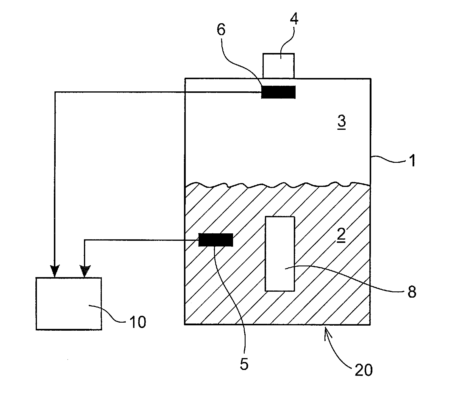
[0032]FIG. 1a shows an example of an insulating liquid filled apparatus 20 including a device for detecting malfunction of the apparatus according to an embodiment of the invention. The insulating liquid filled apparatus 20 includes a container 1 containing insulating liquid 2 and gas 3. The insulating liquid 2 has suitable dielectric and cooling properties. The insulating liquid 2 has a surface forming an interface between the insulating liquid 2 and the gas 3. The insulating liquid filled apparatus 20 further includes an electric unit 8, such as a tap changer, which is enclosed within the container 1 and is completely submerged in the insulating liquid 2. The electric unit 8 performs operation in which heat is produced and where the insulating liquid 2 can be decomposed into gases. The insulating liquid filled apparatus 20 is provided with a communication unit 4, such as a dehydration breather, which is positioned at the rim of the container 1. The communication unit 4 provides co...


PUM

PropertyMeasurementUnit
relative humidityaaaaaaaaaa
humidityaaaaaaaaaa
temperatureaaaaaaaaaa

Abstract

A method for determining the relative humidity of an insulating liquid filled electric apparatus including a container containing insulating liquid and gas, a communication unit providing communication between the gas of the container and gas of an external environment, and providing dehydration of gas passing through the communication unit, wherein the method includes: continuously measuring and storing the relative humidity of the gas in the container, calculating an average value of the relative humidity in the gas based on the stored humidity measurements during a certain time period, and determining the relative humidity of the insulating liquid based on the average value of the relative humidity in the gas and a relationship between the relative humidity of the gas and the relative humidity of the insulating liquid at equilibrium.

Description

CROSS-REFERENCE TO RELATED APPLICATIONS[0001]The present application is a continuation of pending International patent application PCT / EP2009 / 053150 filed on Mar. 17, 2009 which designates the United States and claims priority from European Patent application 08155250.7 filed on Apr. 28, 2008, the content of which is incorporated by reference.FIELD OF THE INVENTION[0002]The present invention relates to a method and a device for determining the relative humidity of an insulating liquid filled electric apparatus comprising a container containing insulating liquid and gas, a communication unit providing communication between the gas of the container and gas of an external environment, and providing dehydration of gas passing through the communication unit.BACKGROUND OF THE INVENTION[0003]An insulating liquid filled electric apparatus, such as a transformer, a tap changer or switchgear, is an apparatus used in application where isolation and cooling are required. An electric unit is sub...

Claims


Application Information

Patent Timeline
Patent Type & Authority Patents(United States)
IPC IPC(8): G01N33/00H01H19/00G01N33/28H01F27/14H01F27/40
CPCG01N33/2847H01F27/14H01F27/402G01N33/0031H01F2027/404H01F2027/406
Inventor ANDERSSON, GUNNARSTENESTAM, BENGT-OLOF
Owner HITACHI ENERGY LTD
Why Eureka
Try Eureka