
Sign construction with sectional sign assemblies and installation kit and method of using same

a sectional and sign assembly technology, applied in the direction of identification means, lighting and heating apparatus, instruments, etc., can solve the problems of insufficient satisfaction of digital billboards, inconvenient installation of sections, and inability to remove older non-digital billboards, etc., to facilitate routing and securing, facilitate the installation of plurality, and facilitate the mounting of individual ones

Inactive Publication Date: 2015-06-02
ADTI MEDIA
View PDF169 Cites 29 Cited by
  • Summary
  • Abstract
  • Description
  • Claims
  • Application Information

AI Technical Summary

Benefits of technology

This patent is about a way to turn existing non-electronic billboards into electronic displays. The invention includes a set of frames that can be attached to the billboard, and these frames have spaces designed to hold display panels that show dynamic visual information. A power and data harness connects the frames to a controller box, which manages the display information and provides power to the panels. The panels have LED displays to convert the show information into visible light. The invention also allows for easy replacement of malfunctioning panels, which makes maintenance easier.

Problems solved by technology

Retrofitting non-digital billboards have proven to be expensive, time consuming and labor intensive.
Moreover, simply removing an older non-digital billboard and replacing it with a new digital billboard has not proven entirely satisfactory since older installed, non-digital, billboard panels represent substantial capital outlays making it financially difficult, if not impossible, to discard such panels arbitrarily for replacement with digital panels.

Method used


Image

  • Sign construction with sectional sign assemblies and installation kit and method of using same
  • Sign construction with sectional sign assemblies and installation kit and method of using same
  • Sign construction with sectional sign assemblies and installation kit and method of using same

Examples


Embodiment Construction

[0196]For reference purposes, whenever the term “frontside” is used it will always refer to the front viewing side of any element or component part that will be described hereinafter. Backside always opposes the frontside for any part or portion being discussed and is the reverse of the viewing side. Each surface is defined hereinafter in the following manner as a part frontside / backside.

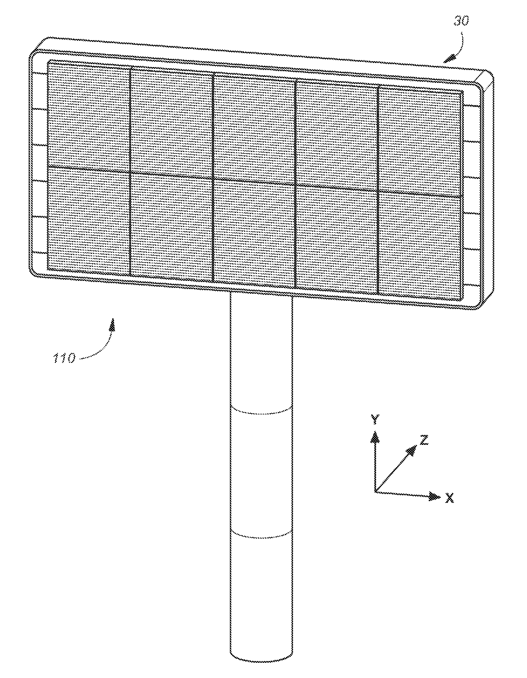
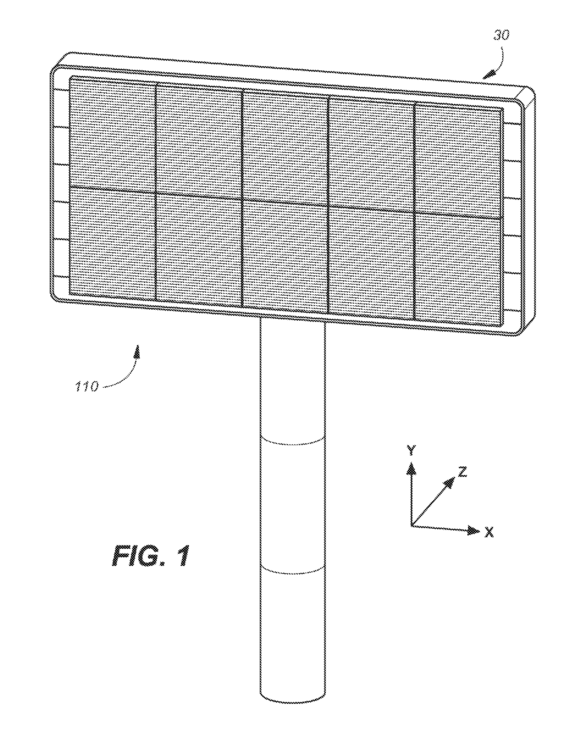
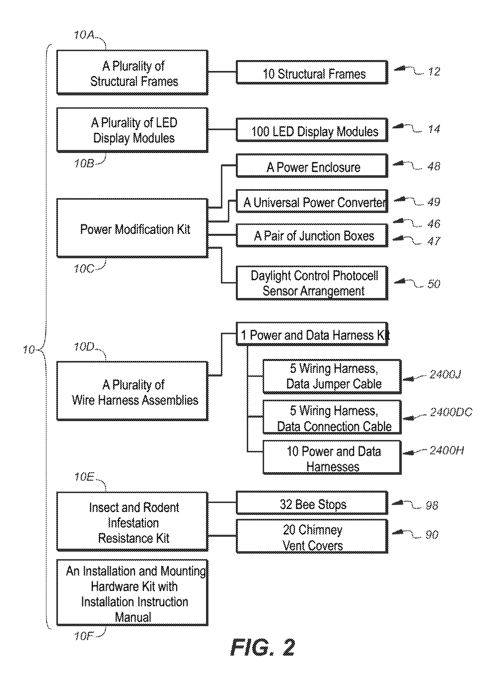
[0197]Referring now to the drawings and more particularly to FIGS. 1 and 2, there is illustrated a self-contained retrofit kit 10 and a resulting dynamic electronic sign or billboard 110 respectively, which kit 10 and which billboard 110 are each constructed in accordance with the present invention. The electronic billboard 110, when constructed in accordance with a novel method of retrofitting or assembling 1010 (FIG. 19) as hereinafter disclosed, is assembled in a fast and convenient manner without the need of special tools or equipment. In short, by use of the in-field retrofit kit 10, a static n...


PUM

PropertyMeasurementUnit
weightaaaaaaaaaa
weightaaaaaaaaaa
distanceaaaaaaaaaa

Abstract

A modification kit for converting an existing signage mounting structure to an electronic sign generally includes a plurality of display modules; a plurality of sign sections each having a front-facing portion and a rear-facing portion, the front facing portion defining a two dimensional array of bays arranged in a plurality of rows along a vertical direction and a plurality of columns along a horizontal direction, each bay configured to receive one of the display modules, the rear-facing portion for mounting to a surface of the existing signage mounting structure; and a plurality of power routing systems, each power routing system having a power input for coupling to a power source and a plurality of power extensions, each power extension for coupling the power source to one of the plurality of display modules. The modification kit when installed provides the electronic sign.

Description

RELATED APPLICATIONS[0001]This application is a continuation-in-part of U.S. patent application Ser. No. 14 / 214,778, entitled “Sectional Sign Assembly and Installation Kit and Method of Using Same”, by David Franklin Cox, et al. filed on Mar. 15, 2014 as a continuation-in-part of U.S. patent application Ser. No. 61 / 950,174, entitled “Sectional Sign Assembly and Installation Kit and Method of Using Same”, by David Franklin Cox, et al. filed on Mar. 9, 2014, as a continuation-in-part of U.S. patent application Ser. No. 14 / 075,308, entitled Modular Installation and Conversion Kit for Electronic Sign Structure and Method of Using Same”, by David Franklin Cox, et al. filed on Nov. 8, 2013, as a continuation-in-part patent application of U.S. patent application Ser. No. 14 / 056,017 entitled, “Modular Wire Harness Arrangements and Methods of Using Same for Backside to Frontside Power and Data Distribution Safety Schemes”, by Arne E. Carlson. et al. filed on Oct. 17, 2013, as a continuation-...

Claims


Application Information

Patent Timeline
Patent Type & Authority Patents(United States)
IPC IPC(8): G09F9/30G09F15/00F21S2/00G09F9/302G09F9/33G09F19/22G09F27/00
CPCG09F9/3026G09F9/33G09F19/22Y10T29/5313Y10T29/49002Y10S345/903F21S2/005G09F27/008G09F15/0037G09G3/32G09F19/228G06F3/1446G09F7/18
Inventor COX, DAVID FRANKLINROMANO, RICHARD J.CARLSON, ARNE E.
Owner ADTI MEDIA
Learn More