Color correction to compensate for displays' luminance and chrominance transfer characteristics

a technology of luminance and chrominance transfer, applied in the field of image processing, can solve the problems of chrominance deviation (, hue deviation) within each channel, large table size, etc., and achieve the effects of increasing the maximum image brightness available, reducing table size, and increasing brightness

a technology of luminance and chrominance transfer, applied in the field of image processing, can solve the problems of chrominance deviation (, hue deviation) within each channel, large table size, etc., and achieve the effects of increasing the maximum image brightness available, reducing table size, and increasing brightness

US9049410B2Active Publication Date: 2015-06-02SAMSUNG DISPLAY CO LTD

Image

  • Color correction to compensate for displays' luminance and chrominance transfer characteristics
  • Color correction to compensate for displays' luminance and chrominance transfer characteristics
  • Color correction to compensate for displays' luminance and chrominance transfer characteristics

Examples


Embodiment Construction

[0023]The embodiments described in this section illustrate but do not limit the invention. The invention is defined by the appended claims.

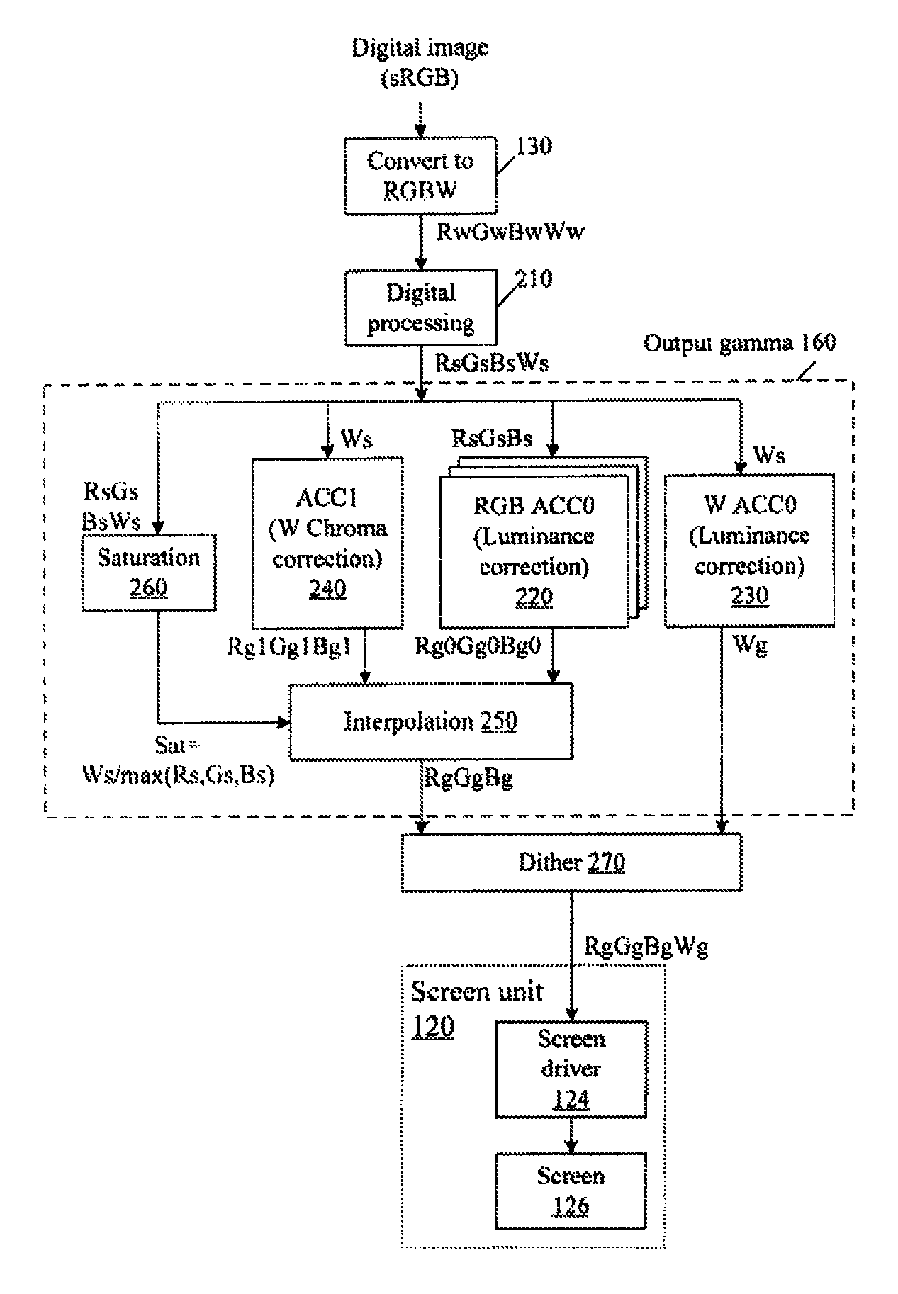
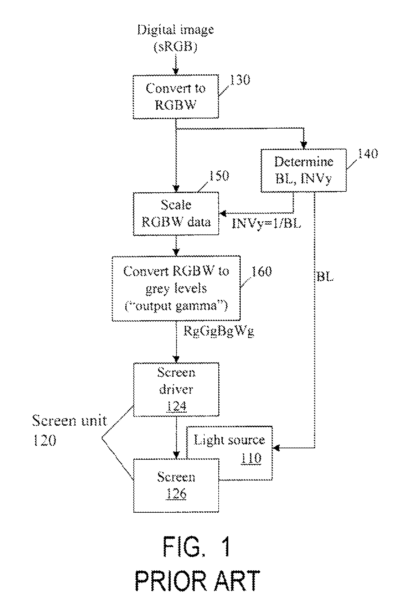
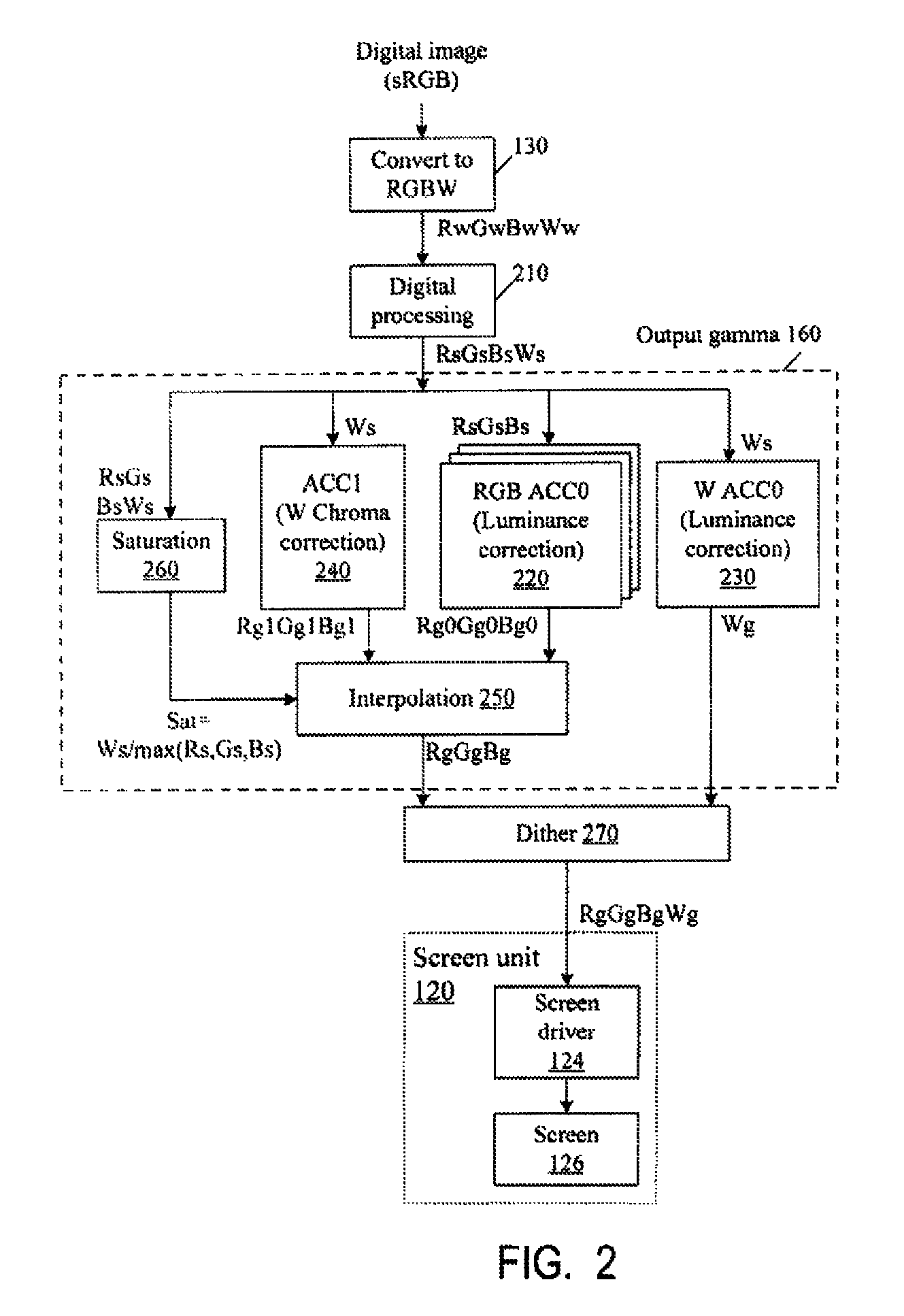
[0024]Some embodiments of the present invention modify the display of FIG. 1 as follows. The color correction is incorporated into the output gamma block 160. The display may or may not use DBLC, and in particular the DBLC block 140 and scaler 150 may or may not be present. Light source 110 may or may not be present, and in particular the display may be non-LCD type. The display may use LUTs or computational circuitry, or combination of the two. For example, some values can be stored in LUTs, white other values can be interpolated from the LUT values. For ease of description, the examples described below use tables, but these examples are not limiting.

[0025]FIG. 2 illustrates a block diagram of a display with such tables 220, 230, 240 in output gamma block 160.

[0026]The color correction technique illustrated in FIG. 2 will be called a “vector met...


PUM


Abstract

Displays are provided with circuitry performing color correction to compensate for the displays' luminance and chrominance transfer characteristics. Some techniques are suitable for RGBW displays and for subpixel-rendered displays. Some displays include an external light source (e.g. a backlight unit in LCDs), and the color correction is coordinated with dynamic control of the light source.

Description

BACKGROUND OF THE INVENTION[0001]The present invention relates to image processing, and more particularly to color correction for displaying an image.[0002]In digital image processing, an image is typically represented as a number of pixels. Each pixel's color is defined by the color's coordinates in some color space, e.g. sRGB. The display converts the color coordinates to “grey levels” which are then used to define electrical signals (e.g. voltages) that determine luminous states of corresponding areas on the screen of the display. (Sometimes, the color coordinates themselves can be used as grey levels.) The luminance displayed in the screen area is some function (called “gamma function”, “gamma transfer function”, “gamma transfer characteristic”, or “gamma curve”) of the corresponding grey level.[0003]For many displays, the gamma function is non-linear, and can be approximated by a power relationship:L=vγ  (1)[0004]where L is the luminance, v is the grey level, and γ is a constan...

Claims


Application Information

Patent Timeline
02 Jun 2015
Publication
US9049410B2
IPC
G09G3/36; H04N1/54; H04N1/60; G09G3/20; H04N5/202; H04N9/69; H04N9/73
CPC
H04N9/73; H04N5/202; H04N9/69; G09G3/2044; G09G3/2074; G09G2300/0452; G09G2320/0233; G09G2320/0242
Inventors
BOTZAS, ANTHONY; BROWN ELLIOTT, CANDICE HELLEN