Method and apparatus of inspecting the upper core shroud of a nuclear reactor vessel

a technology of nuclear reactor and inspection method, which is applied in the direction of nuclear elements, climate sustainability, greenhouse gas reduction, etc., can solve the problems of metal fatigue in the core shroud, erbes patent has some practical problems, and the operator at the top of the reactor containment vessel cannot tell exactly where the sensors are located within the core shroud

Active Publication Date: 2016-02-23
IIA NUCLEAR SERVICES INC
View PDF7 Cites 4 Cited by
  • Summary
  • Abstract
  • Description
  • Claims
  • Application Information

AI Technical Summary

Problems solved by technology

As a result of the wide variations in temperature and pressure, metal fatigue could occur in the core shroud.
However, the invention as shown in the Erbes patent has some practical problems.
Because of the slippage of the tractor drive wheels, the operator at the top of the reactor containment vessel cannot tell exactly where the sensors are located within the core shroud.
Hence, space at the top of the reactor container vessel is limited.
One of the problems that existed for prior inspection methods of a core shroud is that they required a ring to be mounted all the way around the top of the core shroud, typically on the steam dam.
This meant a lot of room had to be taken at the top of the reactor containment vessel during the period of shut down, which is when other people are needing space to perform their functions.
Also, the shroud at the steam dam was not perfectly circular and many times the rings would not fit on the steam dam.

Method used


Image

  • Method and apparatus of inspecting the upper core shroud of a nuclear reactor vessel
  • Method and apparatus of inspecting the upper core shroud of a nuclear reactor vessel
  • Method and apparatus of inspecting the upper core shroud of a nuclear reactor vessel

Examples


Embodiment Construction

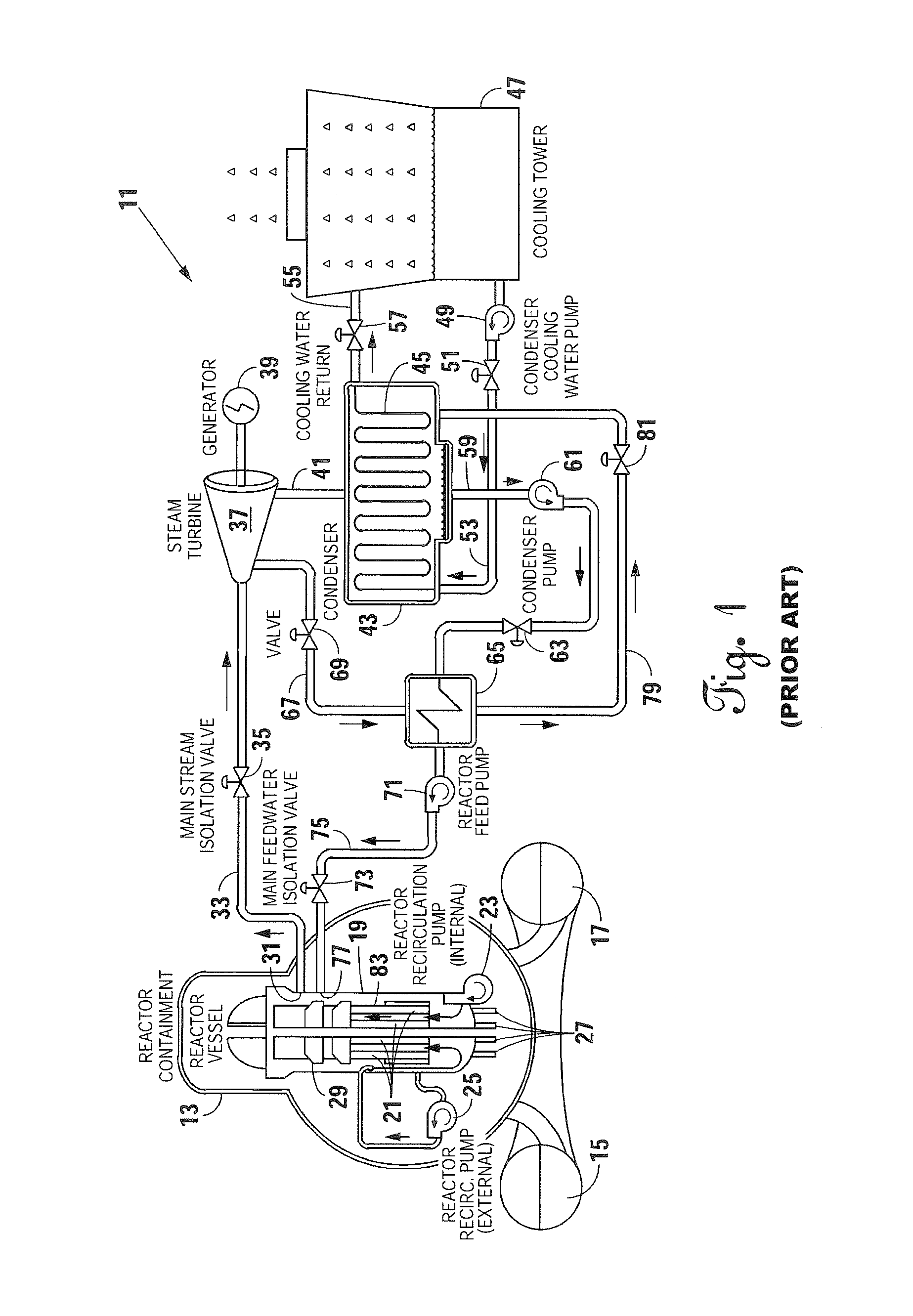
[0022]An illustrative flow diagram for a nuclear power plant for generating electricity is shown in FIG. 1 and is represented generally by reference numeral 11. The nuclear power plant 11 has a reactor containment vessel 13 that has a torus 15 with an auxiliary water feed 17, which is a backup water supply for the nuclear power plant 11.

[0023]Inside of the reactor containment vessel 13 is located a reactor pressure vessel 19. A bundle of fuel rods 21 absorb a neutron to cause nuclear fission and releases of other neutrons. The nuclear fission heats the water contained within reactor pressure vessel 19 to convert the water to steam.

[0024]To ensure the bundle of fuel rods 21 remain immersed in water an internal reactor recirculation pump 23 continues to recirculate water over the bundle of fuel rods 21. Also, an external reactor recirculation pump 25 circulates water within the reactor pressure vessel 19 to ensure the bundle of fuel rods 21 remain cool and immersed in the water.

[0025]...


PUM


Abstract

A method and apparatus for inspecting the upper portion of a core shroud of a nuclear power plant is provided. The upper shroud scanner mounts on an arcuic section of a steam dam of the core shroud and moves back and forth there along. A vertical arm with transducers thereon extend down from a Y-car portion of the upper shroud scanner. Transducers adjacent the core shroud emit and receive an ultrasonic sound to inspect for flaws and defects in the core shroud.

Description

BACKGROUND OF THE INVENTION[0001]1. Field of the Invention[0002]The invention relates to a method and apparatus of inspecting welds and, more particularly, inspecting welds in an upper core shroud of a reactor vessel of nuclear power plant.[0003]2. Description of the Prior Art[0004]In a nuclear power plant, the nuclear reaction occurs inside of a reactor containment vessel which further has a reactor vessel therein. Inside of the reactor vessel is located a core shroud in which a nuclear reaction occurs. The inside of the core shroud is subjected to wide variations in temperature and pressure. As a result of the wide variations in temperature and pressure, metal fatigue could occur in the core shroud. To ensure that does not occur, or monitor potential problems if they do occur, there are requirements by the Nuclear Regulatory Commission that the core shroud be periodically inspected, especially any welds in the core shroud.[0005]In the past, various types of inspection devices for ...

Claims


Application Information

Patent Timeline
Patent Type & Authority Patents(United States)
IPC IPC(8): G21C17/07G21C17/007
CPCG21C17/007Y02E30/30
Inventor VILLAGOMEZ, RAMON, O.
Owner IIA NUCLEAR SERVICES INC
Why Eureka
Try Eureka