Unlock instant, AI-driven research and patent intelligence for your innovation.

Apparatus and method for power management of a system of indicator light devices

a technology of indicator light and power management, applied in the direction of traffic control system, signalling system, instruments, etc., can solve the problems of increasing installation cost, still hard wired, and significant cost of installing network cabling, so as to avoid the cost and disruption of installing network cables, increase installation cost, and reduce the effect of installation cos

Active Publication Date: 2016-03-15
BANNER ENG
View PDF23 Cites 6 Cited by
  • Summary
  • Abstract
  • Description
  • Claims
  • Application Information

AI Technical Summary

Benefits of technology

The present invention solves the problem of high installation costs and limited installation options for facilities using indicator lights that require a hard-wired connection to a power source. The invention allows for the use of wireless components that avoid the need for network cables and battery power, which can exhaust batteries in a short time. The technical effects of the invention include reduction of installation costs and improved installation options.

Problems solved by technology

For facilities using indicator lights in which the indicator lights and other system components are networked, the cost of installing network cabling can be significant.
While wireless components help avoid the cost and disruption of installing network cables throughout a facility, many systems that use indicator lights are still hard-wired to power sources because of power requirements.
Unfortunately, having to connect the indicator lights to a power source increases installation cost and limits installation options, and even precludes their use in some facilities.
While the indicator lights and other components may be powered by batteries, this alternative is not entirely satisfactory for some applications because the power required by an indicator light can exhaust a battery in an impractically short time.

Method used


Image

  • Apparatus and method for power management of a system of indicator light devices
  • Apparatus and method for power management of a system of indicator light devices
  • Apparatus and method for power management of a system of indicator light devices

Examples


implementation example

[0100]Device Implementation Example

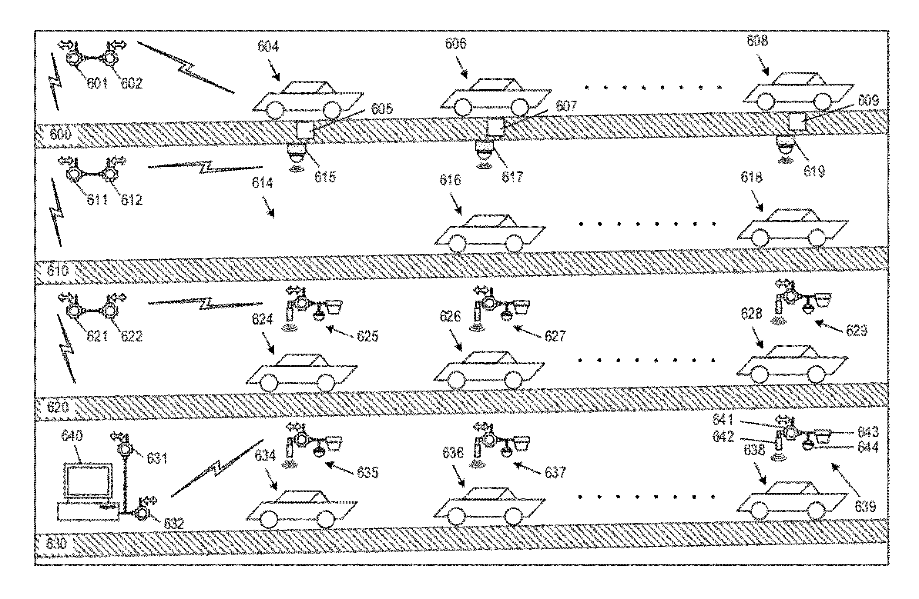
[0101]FIG. 22 is a plan view of an implementation of the wirelessly networked indicator light device 200 of FIG. 2 in the form of a unitary device assembled from interconnected modules. A battery module 320 illustratively containing four (4) D-cell alkaline batteries or lithium batteries serves as the base of the device, and is used to mount the device to any suitable surface from the bottom or side surfaces of the battery module 320. A battery module cover 322 completes the battery module 320. A data radio module 330 and a light and sensor module 340 are mounted to the battery module cover 322 in any suitable manner, illustratively by respective externally threaded conduits which project from the data radio module 330 and the light and sensor module 340 through respective holes in the battery module cover 322 and are secured by respective nuts. The light and sensor module 340 includes an embedded ultrasonic sensor 344 for emitting ultrasonic waves...


PUM


Abstract

Indicator light devices are useful in many applications for indicating properties of physical spaces respectively associated therewith and in physical proximity thereto. The indicator light devices are network-enabled and self-powered, and capable of participating in coordinated power-managed operation to provide a sufficient service life and lower installation and replacement costs. The indicator light devices may be used with or without associated sensors. The various embodiments described herein use various power management techniques singly or in combination to greatly increase the service life of self-power indicator light devices without diminishing their effectiveness in the application. These techniques include operating only the indicator light devices associated with the physical spaces having properties of interest, operating the indicator light devices with synchronized flashing, operating the indicator light devices in accordance with the detection of specific conditions, relevant time operation, in-vicinity activation, and ambient light responsiveness.

Description

BACKGROUND OF THE INVENTION[0001]1. Field of the Invention[0002]The present invention relates to indicator light devices, and more particularly to power management of a system of indicator light devices.[0003]2. Description of Related Art[0004]Indicator lights are used in a variety of different types of systems for indicating a condition existing in a physical space associated with and in physical proximity to the indicator light. Indicator lights are commonly employed, for example, in smart parking systems. Smart parking systems have become popular in Asia, Europe and most recently in the United States. These systems are typically used in enclosed parking structures such as parking ramps to maximize parking utilization and increase revenue for the operator (a ramp operator, for example), and to improve the user's (a retail customer, for example) experience. One type of smart parking system uses a vehicle sensor and an indicator, typically an LED light, in proximity to each parking ...

Claims


Application Information

Patent Timeline
Patent Type & Authority Patents(United States)
IPC IPC(8): G08B5/22G08G1/14
CPCG08G1/146G08G1/142G06F1/3206
Inventor FAYFIELD, ROBERT T.MARJAMAA, ROMAN YORK
Owner BANNER ENG