Modular footwear display apparatus

a technology of footwear display and module, which is applied in the field of footwear display apparatus, can solve the problems of limited flexibility of these devices to integrate with existing shoes in a non-destructive, easily customizable and broadly ornamental manner, and the removal of the shield may require the removal of the shoe and the laces, so as to achieve more customization of the appearance of footwear, easy management of the display, and easy to control the effect of the

Inactive Publication Date: 2016-04-05
JASMINE ELIJAH CLEMENTY
View PDF10 Cites 21 Cited by
  • Summary
  • Abstract
  • Description
  • Claims
  • Application Information

AI Technical Summary

Benefits of technology

[0026]It is an object of this invention to provide a means to display image based footwear adornments on footwear in a more customizable and dynamic manner. The invention herein allows more customization of footwear appearance with easily manageable control over the display of one or multiple foot display modules.
[0027]It is yet another object of this invention to provide a means to synchronize information from multiple modules. This enables a broader, more dynamic and interactive presentation for users of ornamental attachments of footwear.
[0028]It is yet another object of this invention to provide a more effective means of rapidly and securely attaching and detaching a display device to the laces of a shoe. This is done by means of a novel attachment bar element having an L-shape. This allows the person using it to easily attach the apparatus underneath the laces and snap it into a data port receptacle, which securely fastens the device to the foot wear and conceals the data port simultaneously.

Problems solved by technology

While many of these inventions achieve a desired level of customization, the flexibility of these devices to integrate with existing shoes in a non-destructive, but easily customizable and broadly ornamental manner is limited.
However, current inventions that bind ornamental attachments to the laces region of shoes have some deficiencies, related to their ease of use.
While, this is an effective means of binding the object to the laces, individually manipulating the laces to fit in grooves or holes may be considerably time consuming for detachment of the shield.
Further, removal of the shield may require the removal of the shoe and laces.
While 2008 / 0288317 has an innovative mechanism to secure some types of objects to footwear, there remain some problems associated with the the design of the fastening mechanism and others with it's capability of displaying and modifying ornamental designs on footwear.
For example, the presence of three raised sections on the dorsal side of the element, (one at the distal end, one middle section forming a groove near the distal end, and one at the proximal end) also prevent easy removal and of the device from underneath the laces.
In particular the raised middle section, while ostensibly forming a groove that stabilizes the element, may also prevent the device from being easily inserted and removed from under the laces.
Additionally, the elastic sleeve which is required to bind the nominal object to the base element would likely cover any desired interchangeable ornamental design and thus render the device ineffective for stylistic and personalization that is desired for the footwear.
Similar to the Valteau patent, individually manipulating the laces to fit through the mount may be considerably time consuming for detachment of the entire apparatus from the footwear.
Further, the placement of the LCD screen at the top of the tongue may be undesirable for several reasons (1) the top of the tongue is in close proximity to the socks of the shoe and as such bacteria may build up on the back side of the LCD display (2) often times the pant leg covers this part of the tongue which may inhibit viewing of the display, (3) when running, the extra wight of the LCD may induce the top of the tongue to flop back and forth, damaging the LCD (4) the close proximity of the LCD to the shin or top of the ankle, may irritate the skin or cause bruising if worn for extended periods of time.
Further, because of the necessity of having a window within the footwear unit, there is a limit to the practical spatial organization that can be achieved (e.g. number of places upon which the programmable display can arranged on the shoe).
For example, specific re-location of the programmable display onto a different area of the same shoe is impractical, because it would require more alterations to the existing shoe (e.g. more windows).
As such, these inventions do not account for the obvious desire to have two (or more) shoe attached programmable displays function as a synchronized inter-related display unit.
Further, buttons may be prone to inadvertent activation by bumping into objects with the footwear.
While it is necessary to have a means by which to attach the programmable display to the footwear unit, each of these mechanisms would likely be have one or more of the following detriments: an overt carrier or pocket may be stylistically undesirable, these attachment mechanisms may involve permanent modifications to the footwear, they also may be susceptible to failures with rigorous foot movement (running) such as in the case of a pocket or adhesive, running, or leave adhesive attached to the surface of the footwear.
However, considering that footwear is regularly subjected to many types of extreme mechanical, heat and moisture related environments and that the proposed display may be include expensive components such as OLED, LCD, wireless sensors, pedometers and global positioning systems, the lack of detail in the specification regarding designs, materials, and / or positioning of elements is not trivial.

Method used


Image

  • Modular footwear display apparatus
  • Modular footwear display apparatus
  • Modular footwear display apparatus

Examples


Embodiment Construction

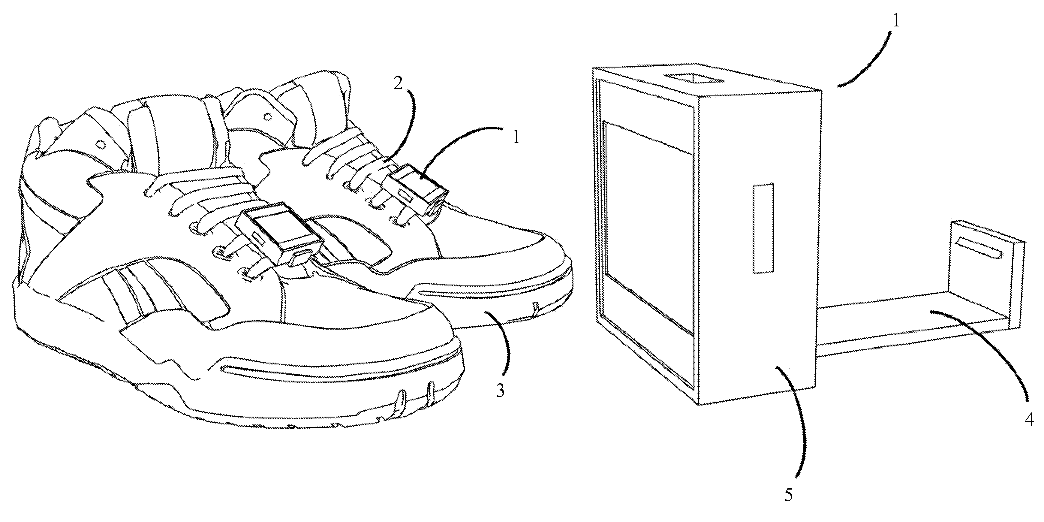
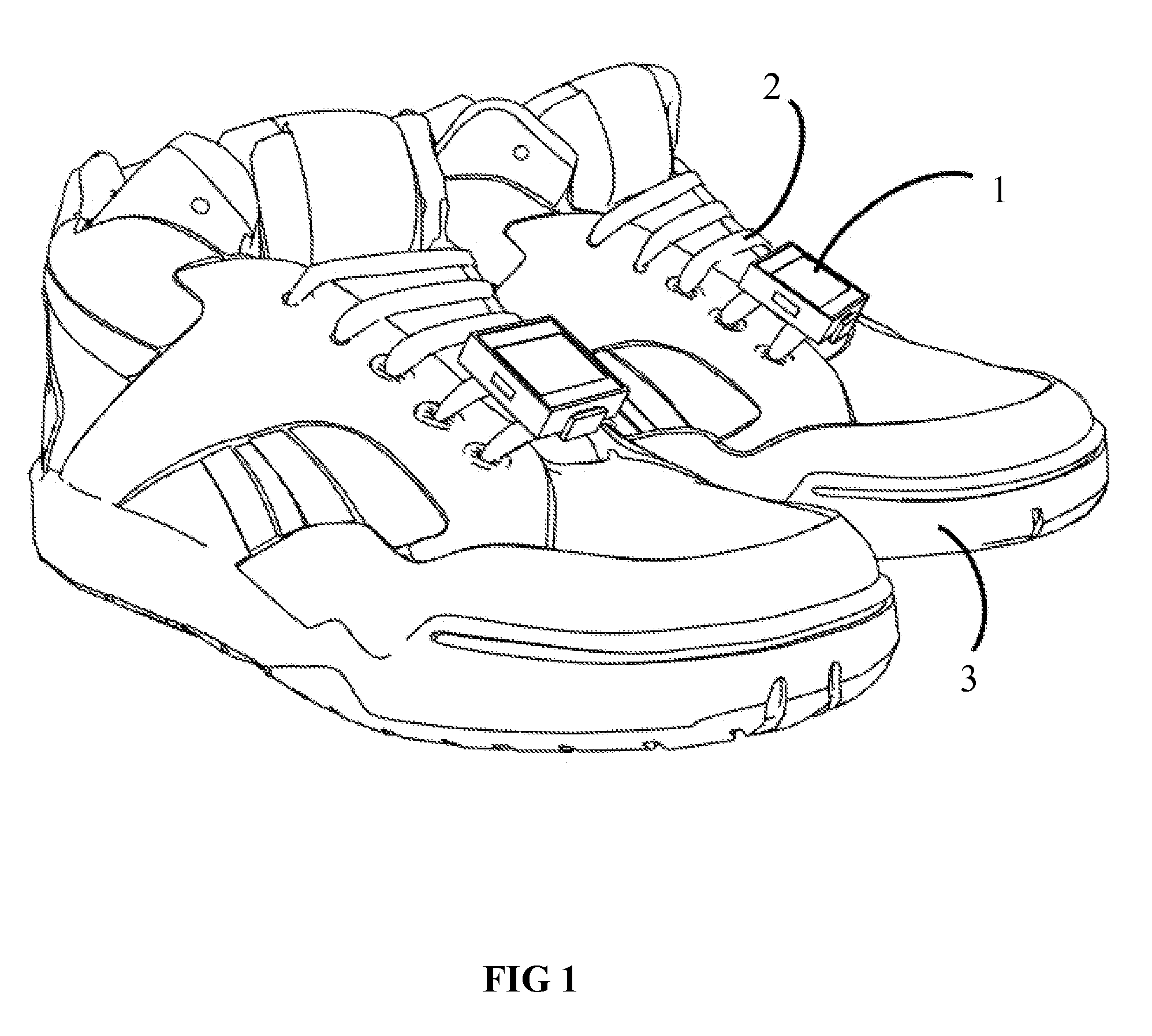
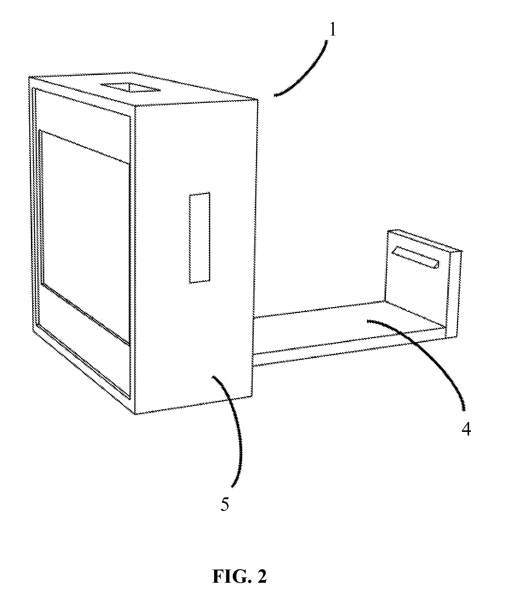
[0038]One or more modular footwear apparatus 1 is designed to attach on to the laces 2 of a shoe 3 or pair of shoes and display images as a reflection of a desired customized display. Each modular footwear apparatus 1 is generally composed of two broad elements an attachment bar element 4 and a display element 5.

[0039]The attachment bar 4 is an L-shaped element composed of an applicator section 6 which is attached to a tab section 7. The attachment bar may be made of a sturdy and flexible material, such as plastic or another synthetic material. It should have a thickness dimension 8 such that it provides resistance to bending, cracking or snapping when pressure is applied during it's use. Also, it should have a width dimension 9 such that it is able to be comfortably manipulated with the fingers and covers a broad area of the shoe's tongue when it is inserted below the laces. It's length dimension 10 should be long enough to extend beyond the display device, but close enough to form...


PUM


Abstract

This invention is a removable module for customization of the display of images, animations or videos on footwear. It may synchronize with other like modules for a more dynamic and broader display across multiple pieces of footwear. In addition, it has a unique and sturdy attachment mechanism comprising a L-shaped attachment bar that locks into the data receptacle of the display. This allows stable binding of the module to footwear when in use and rapid attachment and removal.

Description

CROSS-REFERENCE TO RELATED APPLICATIONS[0001]This application claims a priority benefit to US provisional patent application 2011 / 61505480.STATEMENT REGARDING FEDERALLY SPONSORED RESEARCH OR DEVELOPMENT[0002]Not ApplicableREFERENCE TO SEQUENCE LISTING, A TABLE, OR A COMPUTER PROGRAM LISTING COMPACT DISK APPENDIX[0003]Not ApplicableBACKGROUND OF THE INVENTION[0004]1. Field of the Invention[0005]The present invention is in the technical field of boots, shoes and leggings. More particularly, the present invention is in the technical field of a shoe attachment. More particularly, the present invention is in the technical field of means attached to a foot covering that uses visible radiant energy that is cast back from itself or that originates from itself to make the means visible or cast radiant energy to make the surrounding environment visible.[0006]2. Background of the Art[0007]Customizing and personalizing footwear for either style or utilitarian purposes is a long standing consume...

Claims


Application Information

Patent Timeline
Patent Type & Authority Patents(United States)
IPC IPC(8): A43B23/24A43B3/00
CPCA43B23/24A43B3/0005A43B3/34
Inventor JASMINE, ELIJAH CLEMENTY
Owner JASMINE ELIJAH CLEMENTY
Why Eureka
Try Eureka