Printing apparatus using photocurable ink and method for producing printed material

a printing apparatus and photocurable technology, applied in the field of printing apparatus, can solve the problems of insufficient association of ink with fiber, peeling of cured ink, and inability to print images on printing media using ultraviolet-curable ink in jp a-2010-162754, and achieve the effect of cured photocurable ink

Active Publication Date: 2016-04-12
SEIKO EPSON CORP
View PDF16 Cites 1 Cited by
  • Summary
  • Abstract
  • Description
  • Claims
  • Application Information

AI Technical Summary

Benefits of technology

[0009]An advantage of some aspects of the invention is that the concern of cured ink peeling off and apertures of mesh fabric being blocked is reduced when printing an image on a printing medium using photocurable ink.

Problems solved by technology

However, printing an image on a printing medium using the ultraviolet-curable ink in JP A-2010-162754 has not been considered at all.
That is, there is a tendency for the association of the ink with the fiber to be insufficient.
In addition, since there are a great deal of fibers that have fluff on the surface of the printing medium, in a case in which such a fiber is used, there are cases in which a significant amount of the ultraviolet-curable ink becomes attached to the fluff.
If such a printing medium is commercialized as a product and provided for use as clothing, a packing device or the like, there is concern that a problem arises in which the cured ink tends to peel off as a result of friction or impacts.
In addition, in a case in which the printing medium is a mesh fabric that includes apertures in a lattice shape, problems such as a state in which ink is attached to the edges of the apertures of the mesh fabric and blocking the apertures or the contact area of the ink and the fiber being small can occur from merely discharging ultraviolet-curable ink onto the mesh fabric.
If the ink is cured by irradiating ultraviolet light in this state, there is concern that a problem arises in which the apertures of the mesh fabric become blocked and the cured ink tends to peel off from the mesh fabric.

Method used


Image

  • Printing apparatus using photocurable ink and method for producing printed material
  • Printing apparatus using photocurable ink and method for producing printed material
  • Printing apparatus using photocurable ink and method for producing printed material

Examples


first embodiment

FIGS. 1A to 1E

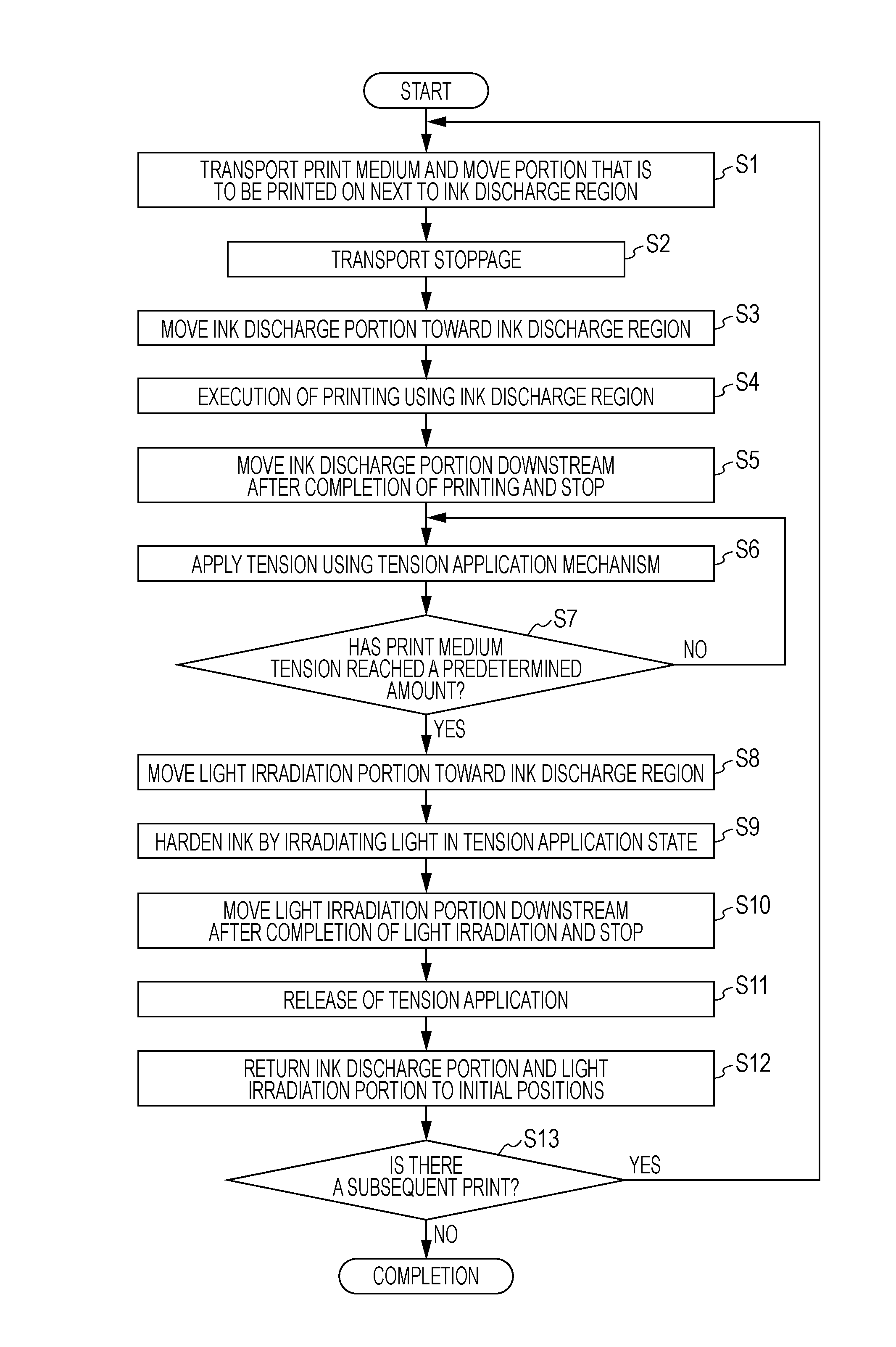
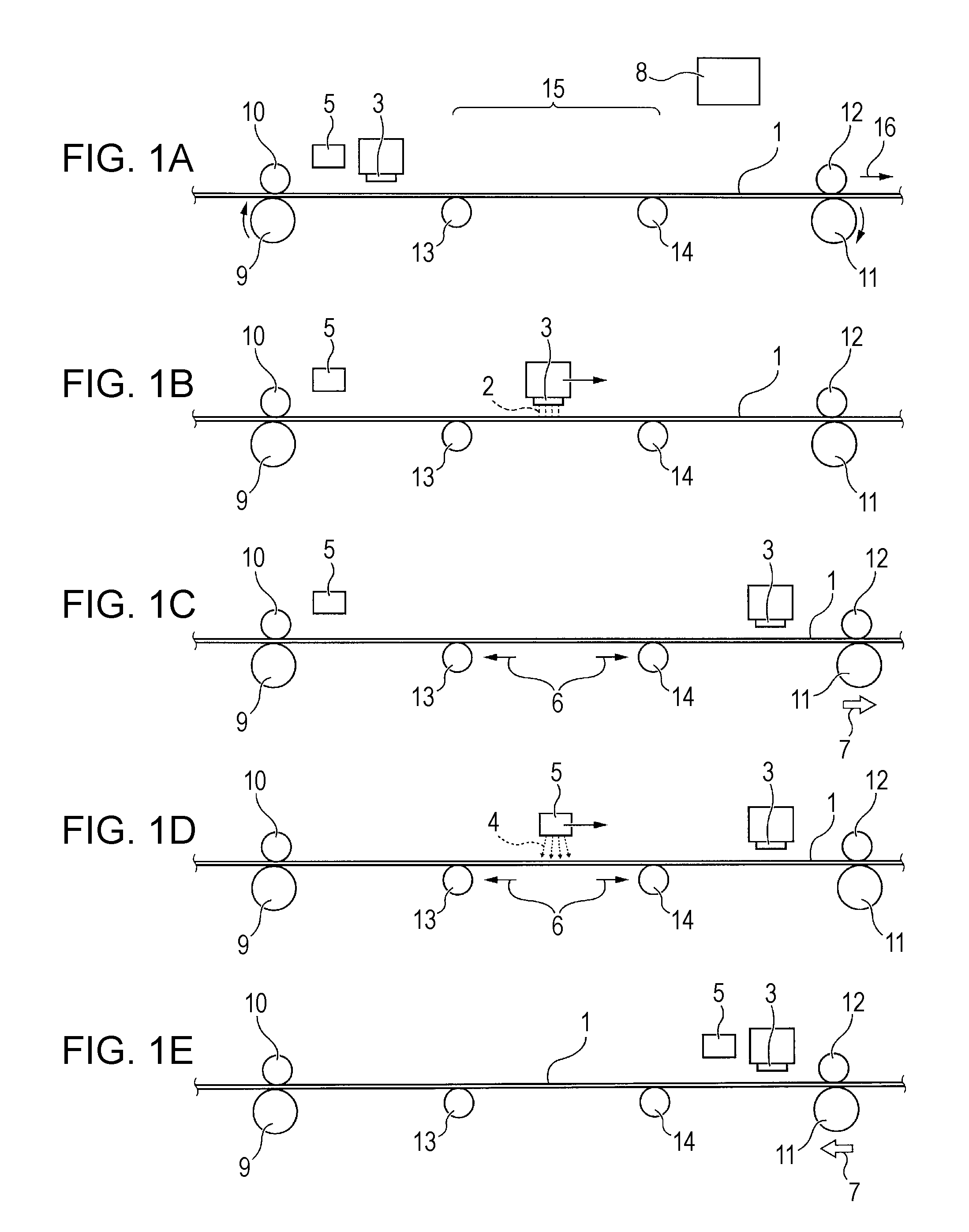
[0044]As shown in FIGS. 1A to 1E, a printing apparatus that uses photocurable ink according to the first embodiment of the invention includes an ink discharge section 3 that discharges ultraviolet-curable ink (referred to as “UV ink” below) 2, which is an example of a photocurable ink, onto a printing medium 1 that is transported, a light irradiation section 5 that irradiates ultraviolet light (referred to as “UV light” below) 4, which is curing light, onto the UV ink 2 that has been discharged onto the printing medium 1, a tension application mechanism 7 that applies a tension to the printing medium 1, and a control section 8 that controls the respective actions of the ink discharge section 3, the light irradiation section 5 and the tension application mechanism 7.

[0045]Further, the control section 8 is configured so as to discharge the UV ink 2 onto the printing medium 1 by controlling the ink discharge section 3, and subsequently apply a tension 6, which is greater ...

second embodiment

FIGS. 2A to 2E

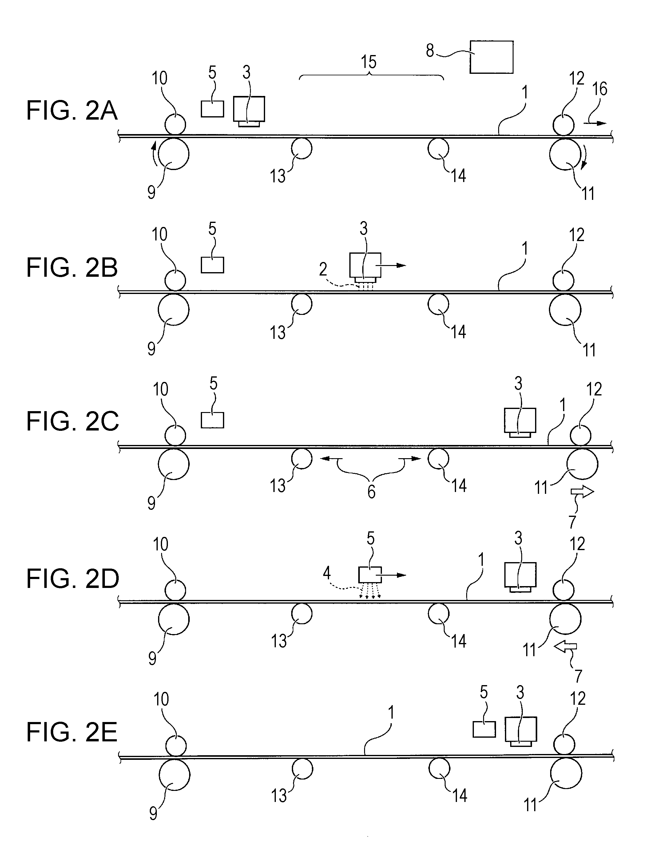
[0068]As shown in FIGS. 2A to 2E, in a printing apparatus that uses photocurable ink according to the second embodiment of the invention, the control section 8 discharges the UV ink 2 onto the printing medium 1 by controlling the ink discharge section 3 (FIGS. 2A and 2B), applies the tension 6, which is greater than that at the time of ink discharge, to the printing medium 1 by controlling the tension application mechanism 7 (FIG. 2C), and subsequently changes to a lower tension application state than that of the high tension 6 that was applied (FIG. 2D) and irradiates UV light 4 onto the UV ink 2 that has been discharged onto the printing medium 1 by controlling the light irradiation section 5.

[0069]Additionally, in the same manner as the first embodiment, the timing of the start of movement of the ink discharge section 3 from the initial position thereof, the timing of the application of the tension using the tension application mechanism 7 or the timing of the remov...

third embodiment

FIGS. 3A to 3E

[0075]As shown in FIGS. 3A to 3E, in a printing apparatus that uses photocurable ink according to the third embodiment of the invention, the light irradiation section 5 is provided integrally with the ink discharge section 3 rather than the two components being formed as separate entities. Since the rest of the configuration of the printing apparatus is the same as the first embodiment, the same reference numerals apply to the same parts and the description thereof will be omitted ((A) to (E) in FIGS. 3A to 3E).

[0076]As shown in FIGS. 3C and 3D, in the embodiment, when UV light 4 is irradiated by the light irradiation section 5 onto the UV ink 2 that has been discharged from the ink discharge section 3 onto the printing medium 1, the printing apparatus is configured such that the integral ink discharge section 3 and light irradiation section 5 is returned to the movement starting position thereof (the position shown by the broken line in FIG. 3D) and the light irradiat...


PUM


Abstract

A recording apparatus that uses photocurable ink includes an ink discharge section that discharges photocurable ink onto a printing medium, a light irradiation section that irradiates curing light onto the photocurable ink that has been discharged onto the printing medium, a tension application mechanism that applies tension to the printing medium and a control section. The control section discharges photocurable ink onto the printing medium by controlling the ink discharge section, and subsequently applies a tension, which is greater than that at the time of ink discharge, to the printing medium by controlling the tension application mechanism, and irradiates curing light onto the photocurable ink that has been discharged onto the printing medium by controlling the light irradiation section in a state in which the tension is being applied to the printing medium.

Description

BACKGROUND[0001]1. Technical Field[0002]The present invention relates to a printing apparatus that uses photocurable ink which includes an ink discharge section that discharges the photocurable ink onto a cloth (printing medium) that is transported, and a light irradiation section that irradiates curing light onto the photocurable ink that has been discharged onto the cloth and a method for producing a printed material.[0003]2. Related Art[0004]Examples of printing apparatuses of the related art that use this kind of photocurable ink include the printer disclosed in JP A-2010-162754. This document discloses a structure which uses ultraviolet-curable ink and includes an ultraviolet irradiation section.[0005]However, printing an image on a printing medium using the ultraviolet-curable ink in JP A-2010-162754 has not been considered at all.[0006]If ultraviolet-curable ink is discharged onto a printing medium, the ink becomes attached to the surface of the printing medium and there is l...

Claims


Application Information

Patent Timeline
Patent Type & Authority Patents(United States)
IPC IPC(8): B41J2/01B41J11/00B41J2/435
CPCB41J11/002B41J11/0015B41J2/435B41J11/00214B41J3/4078B41J15/16
Inventor USUDA, HIDENORIKAMOSHIDA, SHINICHIFUJITA, TAKUYA
Owner SEIKO EPSON CORP
Why Eureka
Try Eureka