
Optical lens

An optical lens and lens technology, applied in the field of optical lenses, can solve the problems of small image distortion, high detail reduction, unable to achieve imaging resolution, etc., and achieve the effect of small distortion, high resolution, and reducing the number of lenses used

Active Publication Date: 2018-11-30
CHANGCHUN INST OF OPTICS FINE MECHANICS & PHYSICS CHINESE ACAD OF SCI
View PDF4 Cites 1 Cited by
  • Summary
  • Abstract
  • Description
  • Claims
  • Application Information

AI Technical Summary

Problems solved by technology

[0003] Various optical lenses in the prior art cannot achieve the performance indicators of high imaging resolution, high detail reduction, small image distortion and guaranteed image authenticity in the case of long-distance monitoring

Method used

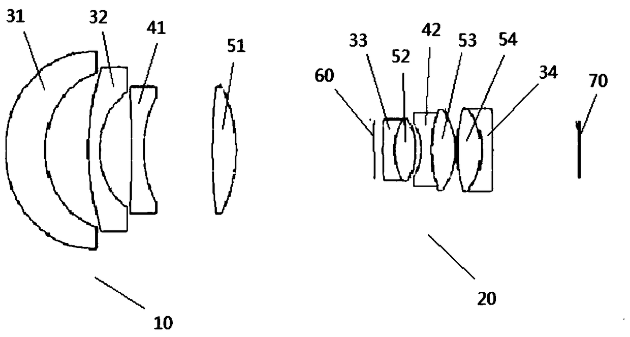
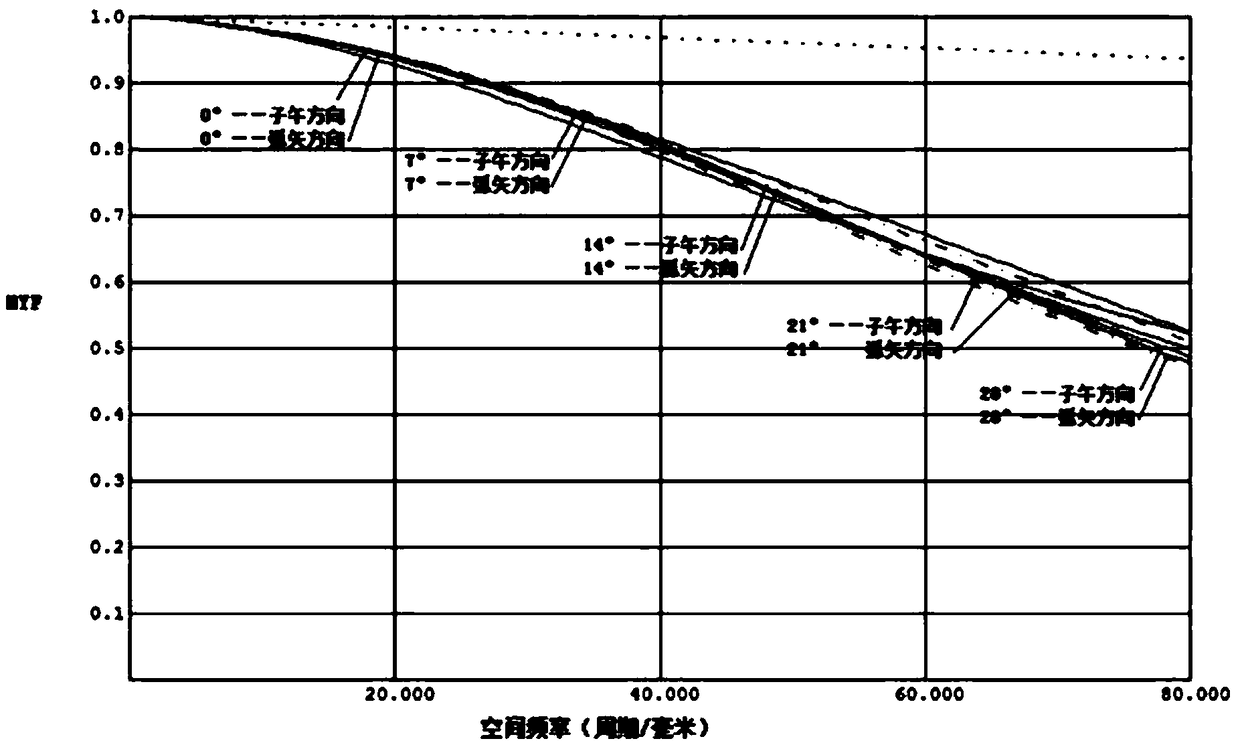
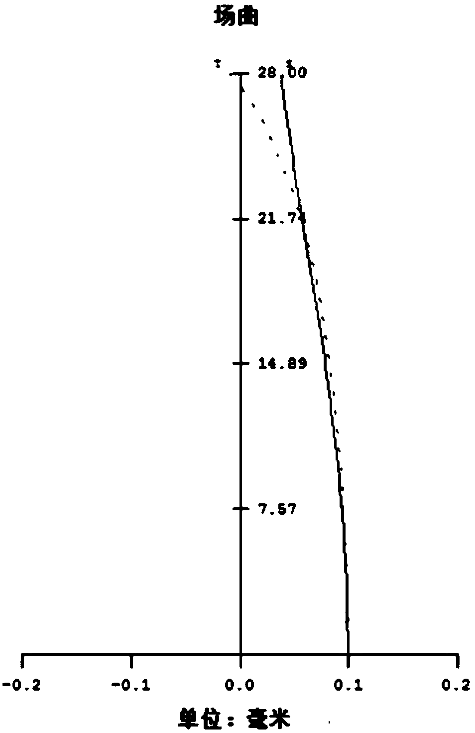

Image

  • Optical lens
  • Optical lens
  • Optical lens

Examples


Embodiment Construction

[0022] Embodiments of the present invention are described in detail below, examples of which are shown in the drawings, wherein the same or similar reference numerals designate the same or similar elements or elements having the same or similar functions throughout. The embodiments described below by referring to the figures are exemplary and are intended to explain the present invention and should not be construed as limiting the present invention.

[0023] In describing the present invention, it should be understood that the terms "center", "longitudinal", "transverse", "length", "width", "thickness", "upper", "lower", "front", " The orientation or positional relationship indicated by "rear", "left", "right", "vertical", "horizontal", "top", "bottom", "inner" and "outer" are based on the orientation or position shown in the drawings The positional relationship is only for the convenience of describing the present invention and simplifying the description, but does not indica...


PUM


Abstract

The invention provides an optical lens comprising a front lens set, a diaphragm and a rear lens set arranged in sequence from an object side to an image side, wherein the front lens set comprises a first negative meniscus lens, a second negative meniscus lens, a first biconcave lens and a first biconvex lens arranged in sequence from the object side to the image side; the rear lens set comprises athird negative meniscus lens, a second biconvex lens, a second biconcave lens, a third biconvex lens, a fourth biconvex lens and a fourth negative meniscus lens arranged in sequence from the object side to the image side; the third negative meniscus lens and the second biconvex lens are hermetically connected and bound to form a first bound lens set; the second biconcave lens and the third biconvex lens are hermetically connected and bound to form a second bound lens set; and the fourth biconvex lens and the fourth negative meniscus lens are hermetically connected and bound to form a third bound lens set. The optical lens provided by the invention has the excellent performance of large relative aperture, large visual field, high resolution ratio and low distortion.

Description

technical field [0001] The invention relates to the field of imaging lenses, in particular to an optical lens with large relative aperture, high resolution, high transmittance and low distortion. Background technique [0002] With the continuous development and improvement of science and technology, the awareness of safety monitoring applied in various fields of social production and life is constantly improving, and the demand for novel high-performance monitoring equipment is also increasing, which promotes the rapid development of related equipment. With the continuous development of mega-high-resolution CCD and CMOS image sensors, more and more attention has been paid to the high-responsivity, high-sensitivity and low-noise ultraviolet-band detectors used in non-traditional visible-near-infrared bands. The demand for band imaging objective lenses is also increasing, especially the requirements for high-definition, high-resolution imaging quality ultraviolet objective len...

Claims


Application Information

Patent Timeline
Patent Type & Authority Applications(China)
IPC IPC(8): G02B13/00G02B13/06G02B27/00
CPCG02B13/0055G02B13/006G02B13/06G02B27/0025
Inventor 吕博姜珊刘伟奇
Owner CHANGCHUN INST OF OPTICS FINE MECHANICS & PHYSICS CHINESE ACAD OF SCI
Learn More