Apparatus and method for forming amorphous coating film

a technology of amorphous coating and apparatus, which is applied in the direction of liquid spraying apparatus, coating, metal material coating process, etc., can solve the problems of difficult to melt completely, limited materials that can be used to form amorphous coating films, and reduced cooling speed, so as to suppress the development of negative pressure in the tubular member, the effect of poor ability to become amorphous and suppressing the rise in the temperature of the base material

Active Publication Date: 2016-07-05
YOSHIKAWAIND CO LTD +1
View PDF18 Cites 0 Cited by
  • Summary
  • Abstract
  • Description
  • Claims
  • Application Information

AI Technical Summary

Benefits of technology

[0011]In order to improve the above-described points, the present invention was accomplished. Namely, the present invention provides an apparatus and a method for forming an amorphous coating film, having the following advantages: a variety of metals, including metals having high melting points and narrow supercooling temperature ranges, can be used to form amorphous coating films; the apparatus can be made compact; and production of oxides is suppressed.

Problems solved by technology

In this high-velocity oxy-fuel flame spray coating, the particles dwell in the flame only for a short time, so that they are difficult to be melted completely.
Moreover, the temperature of the base material rises, so that the cooling speed tends to become lower.
For these reasons, materials that can be used to form amorphous coating films have been limited only to those metals whose melting points are low and whose abilities to become amorphous are great.
Although on-site operation can be done with the apparatus, it is not easy to handle the apparatus.

Method used


Image

  • Apparatus and method for forming amorphous coating film
  • Apparatus and method for forming amorphous coating film
  • Apparatus and method for forming amorphous coating film

Examples


Embodiment Construction

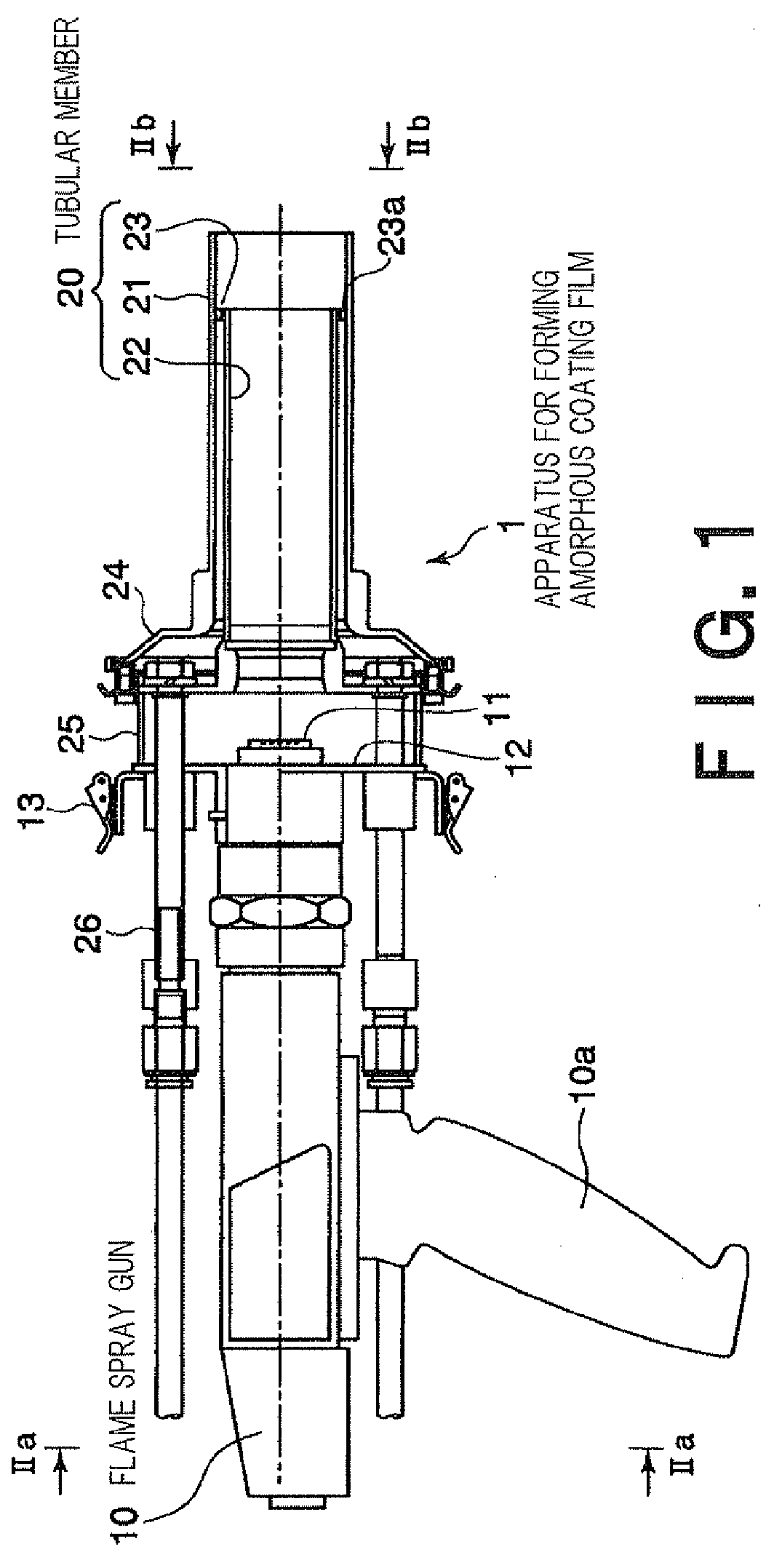
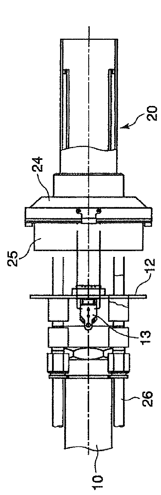
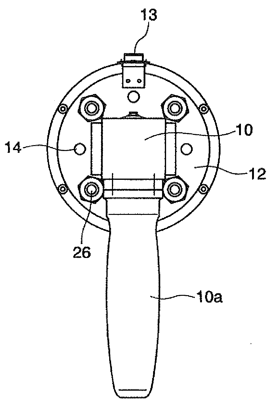
[0063]As FIG. 1 shows, an apparatus for forming an amorphous coating film 1, according to an embodiment of the present invention, comprises a powder flame spray gun 10 having a handle or grip 10a, and a tubular member 20, etc. (that may also be called an external cooling device) attached to the front of the flame spray gun 10. Although not illustrated in the figure, a tube for feeding powder of a flame spray material along with a carrier gas (e.g., a nitrogen gas), tubes for respectively feeding an acetylene gas and an oxygen gas to be used as fuel, and a tube for feeding an internal cooling gas (e.g., a nitrogen gas) are connected to the flame spray gun 10. The flame spray gun 10 has, at its mouth, a nozzle 11 from which flame F and the melted material (the above powder that has been melted) are jetted, as shown in FIG. 3. The internal cooling gas is ejected from a or more positions in contact with the periphery of the nozzle 11, thereby cooling the nozzle 11 and controlling the te...


PUM

PropertyMeasurementUnit
diameteraaaaaaaaaa
supercooling temperatureaaaaaaaaaa
melting pointsaaaaaaaaaa

Abstract

An apparatus for forming an amorphous coating film by jetting flame containing particles of a flame spray material from a flame spray gun toward a base material, causing the particles to be melted by the flame, and cooling both the particles and the flame with the means of a cooling gas before they reach the base material. The apparatus includes a tubular member provided among the path along which the flame is jetted that it surrounds the flame passing through a melting zone in which the particles are melted. The tubular member has a flow channel for the cooling gas, formed along and integrally to the tubular member.

Description

TECHNICAL FIELD[0001]The present invention relates to an apparatus and a method for forming an amorphous coating film on a surface of a base material (substrate) by flame spray coating.BACKGROUND ART[0002]High-velocity oxy-fuel (HVOF) flame spray coating is known as a technique for forming an amorphous phase on a surface of a base material. This technique is as follows. By feeding a fuel and an oxygen gas from the body of a flame spray gun, flame (gas flame) is jetted forward at a high velocity. Particles (powder) of a flame spray material are fed to the flame with the use of a carrier gas. The particles fed to the flame are heated while being accelerated in the flame, strike a surface of a base material along with the flame, and are cooled to be solidified on the surface. Thus, an amorphous coating film is formed on the surface of the base material depending on the type of the metal, which is determined by the components of the particles, and on the cooling speed at which the parti...

Claims


Application Information

Patent Timeline
Patent Type & Authority Patents(United States)
IPC IPC(8): B05B7/20B05B7/16B05D1/10B05C11/00C23C4/06C23C4/12C23C4/14B05B7/22
CPCC23C4/06B05B7/1606B05B7/201B05B7/205C23C4/12C23C4/129C23C4/14B05B7/226B05B7/20
Inventor KURAHASHI, RYUROUKOMAKI, MASAHIROMIMURA, TSUNEHIRO
Owner YOSHIKAWAIND CO LTD
Why Eureka
Try Eureka