Method for manufacturing a molding element by fritting with a completely planar unfritted portion, and corresponding molding element

a molding element and completely unfritted portion technology, applied in the direction of manufacturing tools, solvents, other domestic objects, etc., can solve the problems of stress after the object, deformation of the sintered object, and even more extensive deformation, so as to improve the distribution of the powder

Active Publication Date: 2016-08-09
MICHELIN & CO CIE GEN DES ESTAB MICHELIN
View PDF8 Cites 1 Cited by
  • Summary
  • Abstract
  • Description
  • Claims
  • Application Information

AI Technical Summary

Benefits of technology

[0016]The first step is to form the molding surface of the molding element, namely the surface intended to mold part of the tread of the tire. This first step is performed using laser sintering, making it possible to achieve complex components.
[0018]The method of manufacturing the molding element does not involve a step of detaching the sintered part comprising the molding surface from the non-sintered part that forms the base. The sintered part of the molding element thus remains attached to the non-sintered part of this element and the junction between these two parts is obtained using fused metallic powder. The non-sintered part of the molding element then strengthens the sintered part. The molding element thus carries a low risk of deforming after manufacture, thus guaranteeing that the shell will not leak.
[0021]Thus it is possible for the internal core to rest directly on the base without the need to provide a shell part between this internal core and this base. The time taken to manufacture the sintered part is thus improved. Further, the base delimits the internal core in its bottom part and prevents any non-fused powder from escaping from this core.
[0025]A vent is thus produced in the molding element in a simple and practical way and without having the pierce the shell. Specifically, the passage present in the sintered part is formed layer by layer at the same time as this sintered part. The passage is thus delimited by a wall which isolates it from the cavities belonging to the core. No non-fused metallic powder present in the cavities can therefore escape through this passage. Furthermore, it is possible to use the passage as a means for guiding a piercing means, for example a drill bit, to pierce a hole in the non-sintered part. This then ensures that the hole formed is indeed in the continuation of the passage so as to optimise the ability of the vent to vent air.
[0029]The striations form zones in which powder is stored, thus improving the distribution of this powder over the support plate. It thus becomes easier to obtain layers of powder of constant thickness.

Problems solved by technology

Laser fusing generates thermal expansions within the sintered object and this causes stresses to appear after the object has returned to ambient temperature.
When the sintered object is detached from the support plate, for example during a rapid cutting using a wire, stresses cause the sintered object to deform.
If the sintered object is a solid object then such deformations are even more extensive.
The operation of detaching the molding element from the support plate therefore leads to some degree of deformation of the shell and, in certain extreme cases of deformation, cracks may appear in this shell.
It is thus possible for non-fused powder to escape from these cracks, then leading to a risk of contaminating the tooling and therefore the molded tires and leading to a risk of this powder being inhaled by an operator handling the molding element.
This base does not have a shape that is particularly difficult to achieve.

Method used


Image

  • Method for manufacturing a molding element by fritting with a completely planar unfritted portion, and corresponding molding element
  • Method for manufacturing a molding element by fritting with a completely planar unfritted portion, and corresponding molding element
  • Method for manufacturing a molding element by fritting with a completely planar unfritted portion, and corresponding molding element

Examples


Embodiment Construction

[0043]In the following description, elements that are substantially identical or similar will be denoted by identical references.

[0044]In the present description, the invention is described for the instance in which the molding element is a block of a mold segment. However, it must be noted from the outset that the invention is not restricted to this particular embodiment and may notably be applied to instances in which the molding element is a protrusion, such as a blade or a strip, added on to the radially internal surface of a mold.

[0045]Likewise, the invention is described here for the case where the beam of energy used to sinter the powder is a laser beam. Of course, it is possible to use any other beam of energy, such as a beam of electrons.

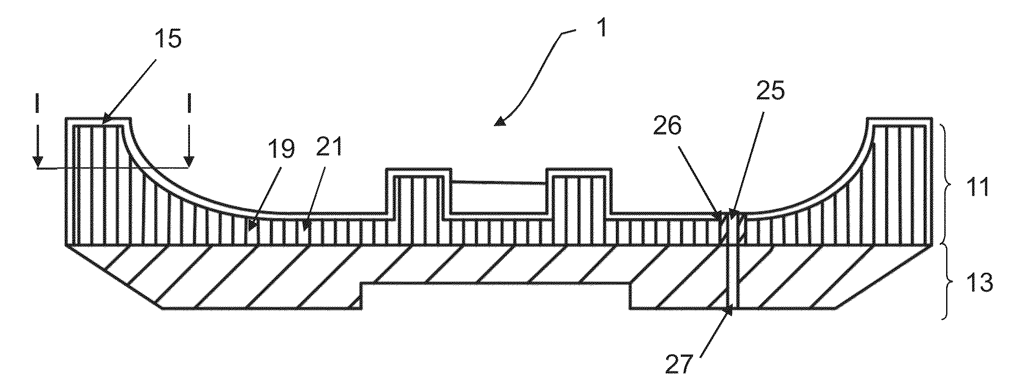
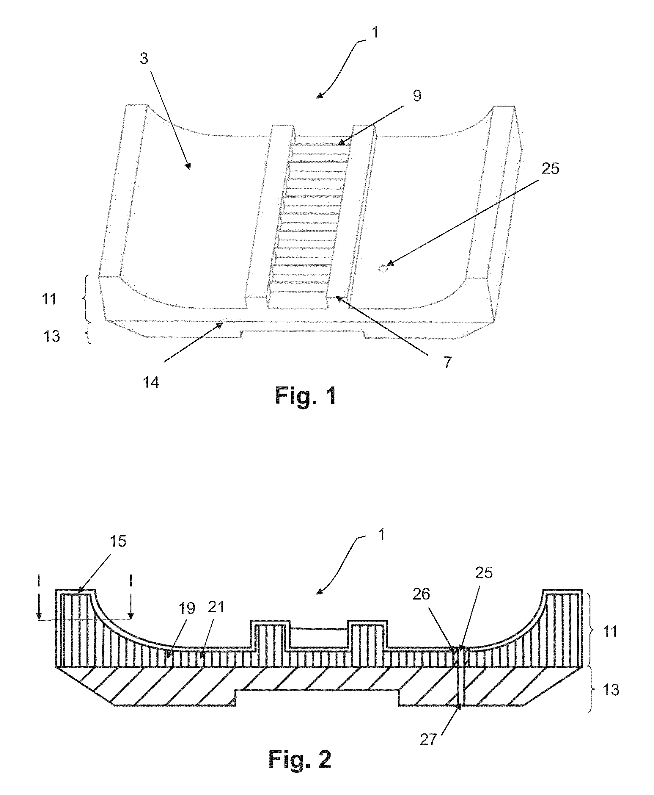
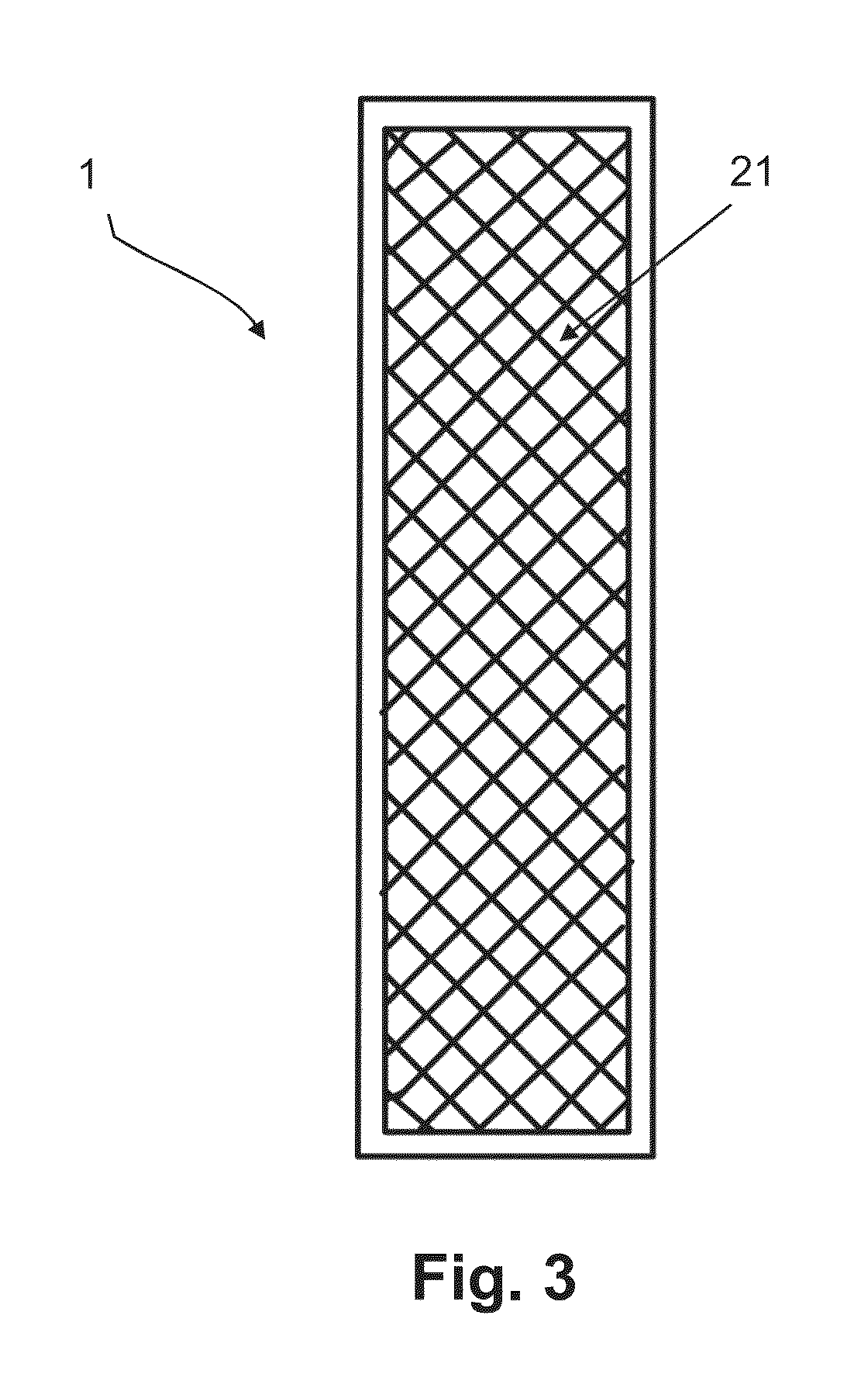
[0046]FIG. 1 depicts a block, denoted by the overall reference 1, of a segmented mold intended for vulcanizing a tire.

[0047]The block 1 comprises a molding surface 3 able to mold part of the tread of the tire.

[0048]More specifically, the mo...


PUM

PropertyMeasurementUnit
widthaaaaaaaaaa
thicknessaaaaaaaaaa
thicknessaaaaaaaaaa

Abstract

The invention relates to a method of manufacturing a molding element for a tire mold. The molding element comprises a sintered part and a non-sintered part attached to the sintered part. The sintered part comprises a shell and a core internal to the shell and formed as one piece with the said shell. The core comprises a meshed structure comprising a plurality of cavities. The method of manufacture comprises a step of manufacturing the sintered part of the molding element from a metallic powder deposited on a flat surface of a support plate and fused layer by layer, the sintered part being attached to the support plate by fused metallic powder. The method also comprises a step of machining the support plate to form the non-sintered part of the molding element.

Description

CROSS-REFERENCE TO PRIOR APPLICATIONS[0001]This application claims the benefit of the filing date of PCT Application No. PCT / EP2012 / 059107, filed May 16, 2012, which claims the benefit of the filing date of the French Application No. 1154252, filed May 17, 2011, each document being incorporated by reference in its entirety for all purposes.BACKGROUND[0002]1. Field[0003]The present invention relates to the manufacture of a molding element by sintering and more particularly to the manufacture of a molding element intended to be arranged in a mold for tires, notably a mold of the segmented type.[0004]2. Description of Related Art[0005]A segmented mold comprises several separate pieces which, by being brought closer together, delimit a molding space of toroidal overall shape. In particular, a segmented mold comprises two lateral shells for molding the sidewalls of the tire and several peripheral segments situated between the shells for molding the tread of the tire. All of these pieces ...

Claims


Application Information

Patent Timeline
Patent Type & Authority Patents(United States)
IPC IPC(8): B29D30/06B23K26/34B22F5/00B22F7/08B23K26/32B23K35/02B22F3/105
CPCB23K26/34B29D30/0606B22F3/1055B22F5/007B22F7/08B29D30/0601B23K35/0244B23K26/32B23K2201/20B29D2030/0614B29D2030/0616B23K2203/50Y02P10/292Y02P10/295B23K2101/20B23K2103/50Y02P10/25B22F10/28B22F10/66B23K26/342B22F3/105B29D30/06B29C67/00
Inventor BONNET, DANIEL
Owner MICHELIN & CO CIE GEN DES ESTAB MICHELIN
Why Eureka
Try Eureka