Inclined phase grating structures

a phase grating and inclination technology, applied in the field of phase grating improvement, can solve the problems of high cost, complicated production of gratings using micro-technical methods, and user's inability to perform measurements at different talbot distances

Active Publication Date: 2016-11-01
KARLSRUHER INST FUR TECH
View PDF26 Cites 10 Cited by
  • Summary
  • Abstract
  • Description
  • Claims
  • Application Information

AI Technical Summary

Problems solved by technology

Since the production of the gratings using micro-technical methods is very complicated, this is very cost intensive.
Moreover, the user does not have the option of performing measurements at different Talbot distances using a predetermined grating set and thus matching the measurement set-up to different sensitivities of the objects to be measured.
A further problem consists in the fact that, depending on the production method, the period can only be maintained to an accuracy of a few nanometers.

Method used


Image

  • Inclined phase grating structures
  • Inclined phase grating structures
  • Inclined phase grating structures

Examples


Embodiment Construction

[0023]In the following description and in the following drawings, the same parts or features in the description and in the drawings are denoted by the same numbers. The drawings are not necessarily true to scale. For reasons of clarity and for making the illustration simpler, some features of the invention can be illustrated in a disproportionately large or schematic fashion; it is likewise accordingly possible that some details of conventional or known elements have not been illustrated.

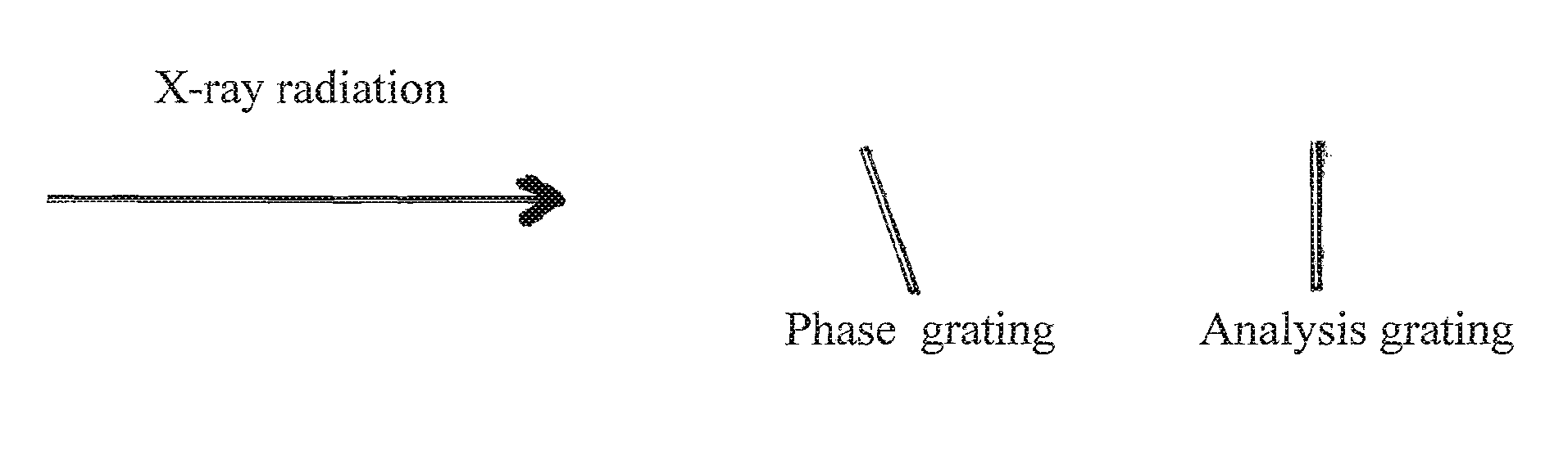
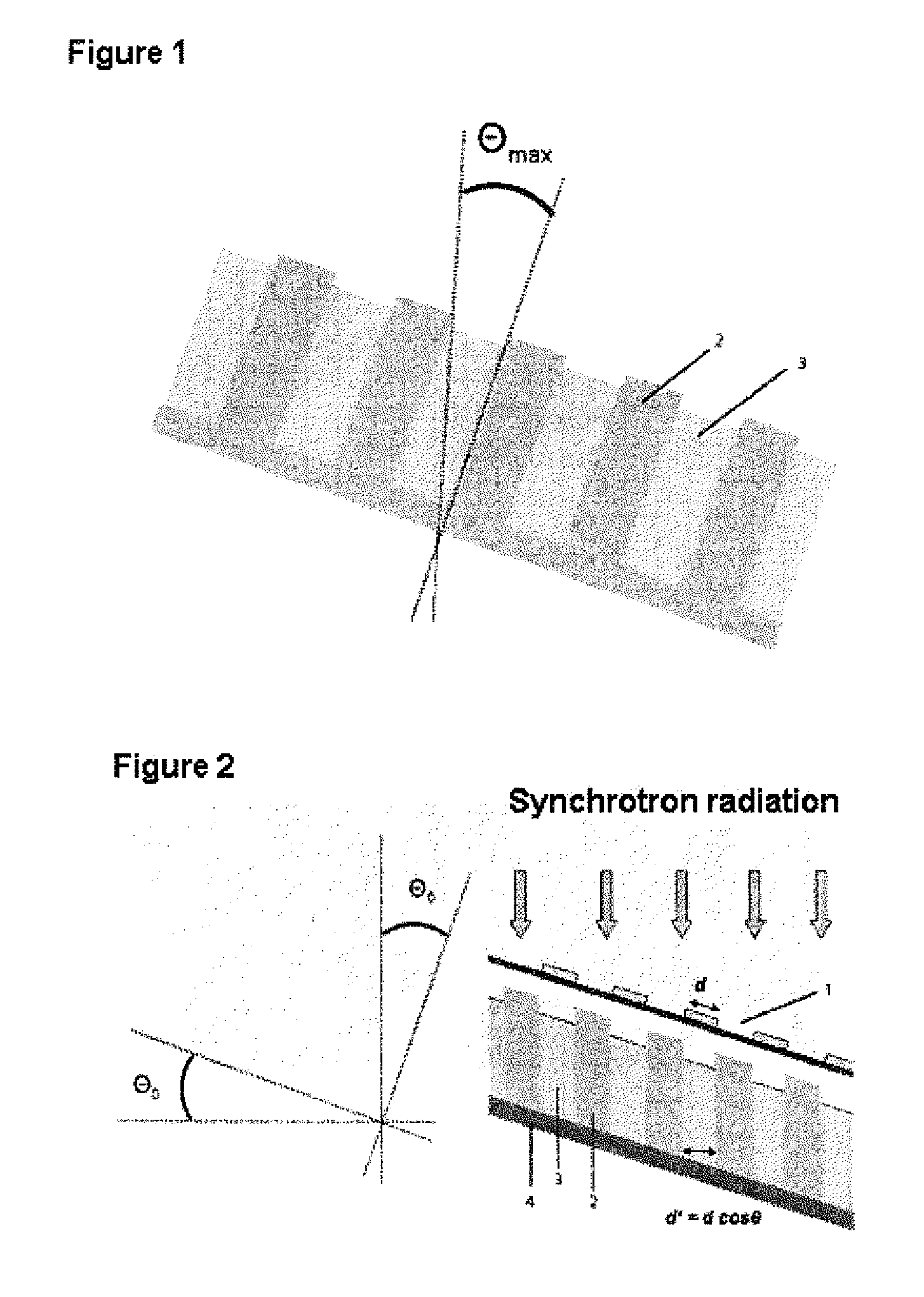
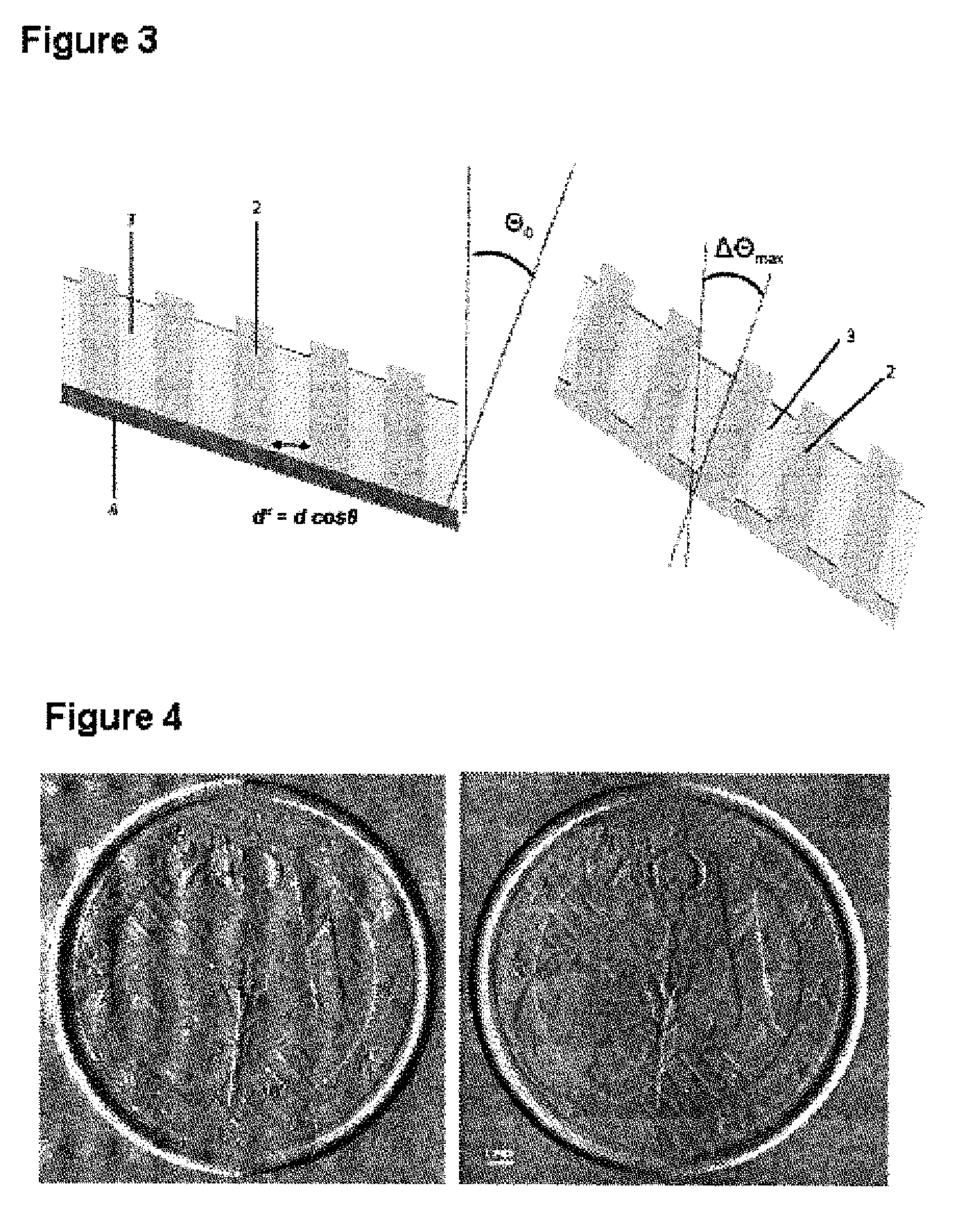
[0024]The subject matter of the present invention relates to grating interferometers with inclined phase grating structures.

[0025]In particular, the inclined grating structures are obtained by[0026]a) inclining the grating structures in the interferometer set-up with respect to the irradiation direction or optical axis, corresponding to a rotation of the grating about the grating central axis which runs parallel to the grating ribs, and / or[0027]b) producing the grating structures at an incline on th...


PUM

PropertyMeasurementUnit
period lengthaaaaaaaaaa

Abstract

Grating interferometer comprising inclined phase grating structures, method for increasing the definition of phase contrast images of interferometers or in applications which are based on the Talbot effect, using inclined phase grating structures, phase gratings wherein the grating structures are positioned at angles on the substrate of the phase grating, method for producing grating structures which are positioned at angles on the substrate of the phase grating, and corresponding uses.

Description

[0001]All documents cited in the present application are incorporated into the present disclosure by reference in their entirety.FIELD OF THE INVENTION[0002]The present invention relates to improvements in the phase gratings in applications that are based on the Talbot effect.TECHNICAL BACKGROUND[0003]Phase-contrast imaging with X-ray beams is based on a grating-based interferometer, which utilizes the Talbot effect for imaging. To this end, two gratings are positioned parallel to one another, perpendicular to the X-ray beam. The phase grating g1 consists of lines which cause a phase shift of π (or π / 2) (π=3.14159 . . . ) and an X-ray absorption that can be neglected. It acts as a beam splitter and divides the X-ray beams into the +1 and −1 diffractive order. The diffracted beams interfere according to the (fractional) Talbot effect and an interference pattern is created, which is periodic in the directions perpendicular to the grating lines. The interference image has a maximum mod...

Claims


Application Information

Patent Timeline
Patent Type & Authority Patents(United States)
IPC IPC(8): A61B6/00G01N23/00G02B5/18A61B6/03
CPCA61B6/484A61B6/4291G01N23/00G02B5/1871A61B6/03A61B6/4092A61B6/502A61B6/504
Inventor MOHR, JUERGENPFEIFFER, FRANZREZNIKOVA, ELENANAZMOV, VLADIMIR
Owner KARLSRUHER INST FUR TECH
Why Eureka
Try Eureka