Check patentability & draft patents in minutes with Patsnap Eureka AI!

Temperature control equipment

a technology of temperature control equipment and equipment, which is applied in the direction of process and machine control, lighting and heating equipment, instruments, etc., can solve the problems of difficult control of airflow, insufficient temperature controllable range of tec, and less than ideal thermal conductivity of air

Active Publication Date: 2016-11-15
CHROMA ATE
View PDF24 Cites 24 Cited by
  • Summary
  • Abstract
  • Description
  • Claims
  • Application Information

AI Technical Summary

Benefits of technology

This solution enables high temperature uniformity, precise control, rapid temperature adjustments, and a wide temperature range, reducing energy consumption and the need for additional temperature feedback components, while being flexible in operating components based on temperature differences.

Problems solved by technology

However, the thermal conductivity of the air is less than ideal, and it is hard to control airflows, so the actual temperature variation and the temperature uniformity of the tested object have rooms for improvement.
Although the performances of the speed of increasing or decreasing temperature and the temperature uniformity of the TEC are good, the temperature controllable range of the TEC is not large enough.

Method used


Image

  • Temperature control equipment
  • Temperature control equipment
  • Temperature control equipment

Examples


Embodiment Construction

[0018]Reference will now be made in detail to the present embodiments of the disclosure, examples of which are illustrated in the accompanying drawings. Wherever possible, the same reference numbers are used in the drawings and the description to refer to the same or like parts.

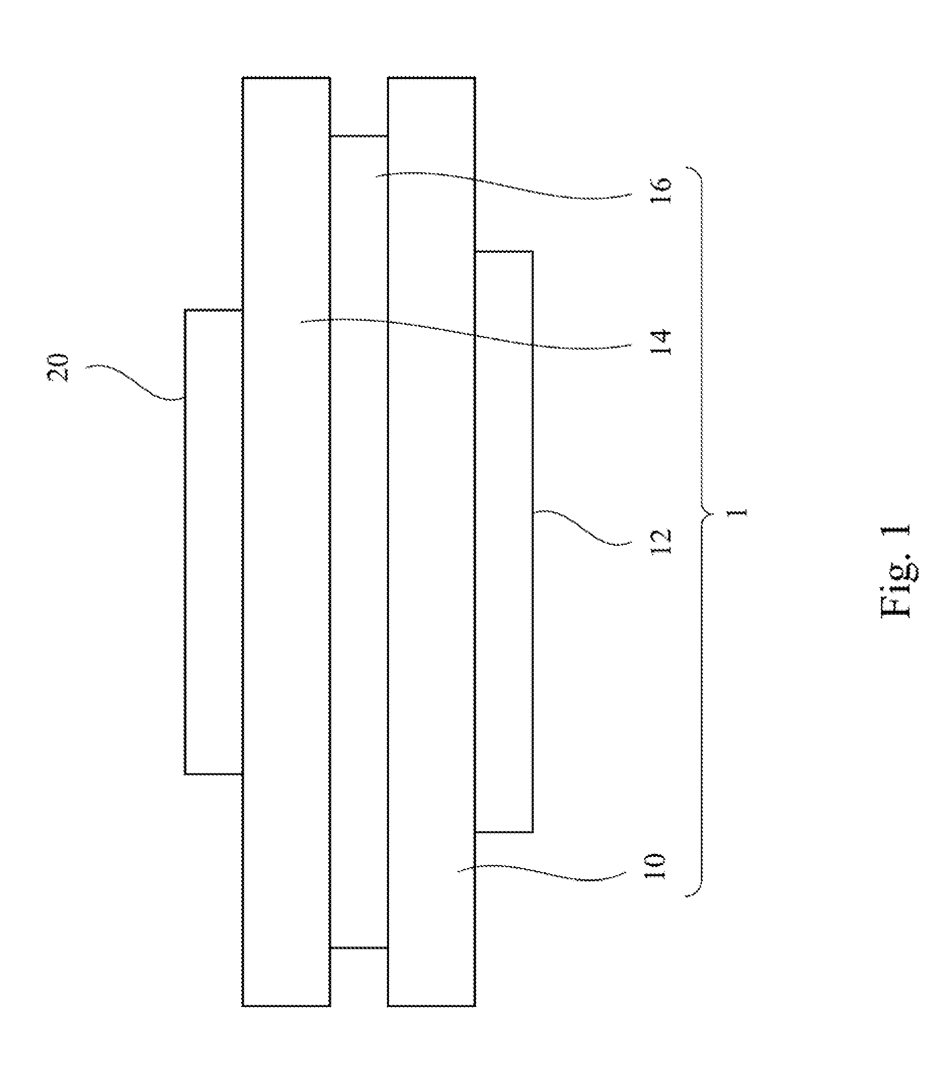
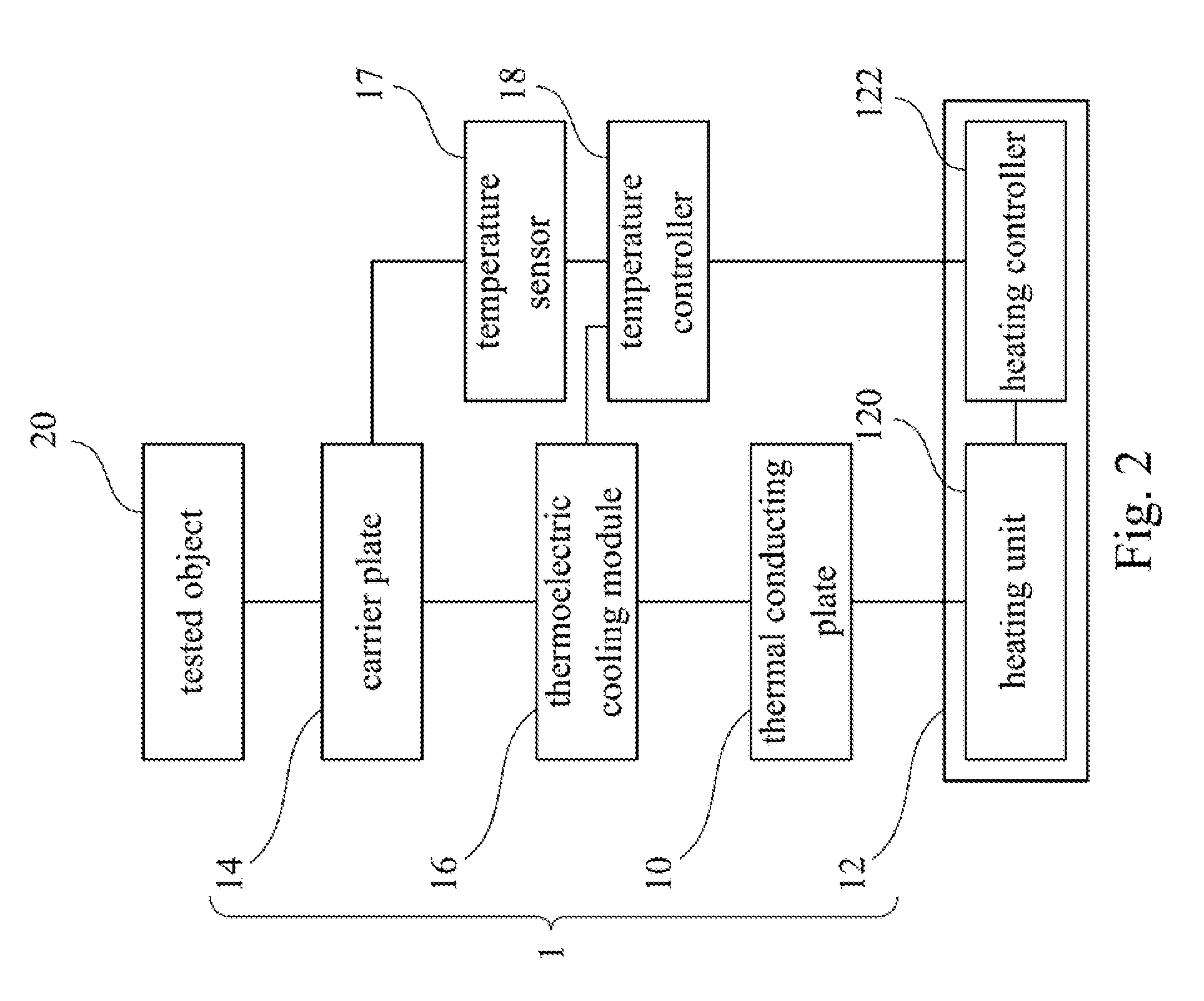
[0019]FIG. 1 is a schematic diagram of a temperature control equipment 1 according to an embodiment of the disclosure. The temperature control equipment 1 is used to control a tested object 20 to a predetermined temperature. The temperature control equipment 1 includes a thermal conducting plate 10, a temperature regulating module 12, a carrier plate 14, and a thermoelectric cooling module 16. The temperature regulating module 12 of the temperature control equipment 1 is thermally connected to the thermal conducting plate 10, and is used to regulate the thermal conducting plate 10 to a reference temperature. The carrier plate 14 of the temperature control equipment 1 is used to accommodate the tested object 2...


PUM


Abstract

A temperature control equipment is capable of controlling a tested object to a predetermined temperature. The temperature control equipment includes a thermal conducting plate, a temperature regulating module, a carrier plate, and a thermoelectric cooling module. The temperature regulating module is thermally connected to the thermal conducting plate for regulating the thermal conducting plate to a reference temperature. The carrier plate is used to accommodate the tested object. The thermoelectric cooling module is thermally connected between the thermal conducting plate and the carrier plate for controlling the tested object to the predetermined temperature via the carrier plate based on the reference temperature.

Description

RELATED APPLICATIONS[0001]This application claims priority to Taiwan Application Serial Number 102123830, filed Jul. 3, 2013, which is herein incorporated by reference.BACKGROUND[0002]1. Technical Field[0003]The present disclosure relates to a temperature control equipment.[0004]2. Description of Related Art[0005]in general, in rapid temperature variation experiments of a tested object, air is usually taken as a medium, and a heat source or a cold source is applied to the tested object in form of airflow. However, the thermal conductivity of the air is less than ideal, and it is hard to control airflows, so the actual temperature variation and the temperature uniformity of the tested object have rooms for improvement.[0006]At present, the developed TEC (Thermoelectric cooler) is a kind of temperature control device capable of precisely controlling temperature. Although the performances of the speed of increasing or decreasing temperature and the temperature uniformity of the TEC are...

Claims


Application Information

Patent Timeline
Patent Type & Authority Patents(United States)
IPC IPC(8): F25B21/02F25B49/00G05D23/19
CPCF25B49/00F25B21/02G05D23/1919
Inventor YU, BEN-MOULIN, MING-CHIEHCHANG, CHING-WENWU, XIN-YI
Owner CHROMA ATE
Features
  • R&D
  • Intellectual Property
  • Life Sciences
  • Materials
  • Tech Scout
  • Unparalleled Data Quality
  • Higher Quality Content
  • 60% Fewer Hallucinations
Learn More