AI technical title is built by PatSnap AI team. It summarizes the technical point description of the patent document.
a rearview mirror and assembly technology, applied in mirrors, instruments, vehicle components, etc., can solve problems such as partial challenges, and achieve the effect of reducing image sticking or ghosting of the compass directional heading display
Active Publication Date: 2017-03-21
MAGNA MIRRORS OF AMERICA INC
View PDF149 Cites 65 Cited by
Summary
Abstract
Description
Claims
Application Information
AI Technical Summary
This helps you quickly interpret patents by identifying the three key elements:
Problems solved by technology
Method used
Benefits of technology
Benefits of technology
[0006]The present invention provides an interior rearview mirror assembly that includes a video display operable to display a compass heading or directional heading of the vehicle (such as responsive to a compass sensor or the like of the vehicle or mirror assembly or to a global positioning system of the vehicle or the like). For such video mirror displays where the cardinal compass directional display (such as N or S or W or E or the like) or intercardinal compass directional display may be displayed for a prolonged period on the video screen in an interior rearview mirror assembly operated and used in a vehicle, particular challenges not overcome by prior imaging sticking suggested solutions can occur. The video display in accordance with an aspect of the present invention is operable to adjust the displayed compass heading to limit or mitigate or reduce image sticking or ghosting of the compass directional heading display.
[0007]According to an aspect of the present invention, an interior rearview mirror assembly for a vehicle includes a mirror reflective element and a video display device disposed behind the mirror reflective element and operable to display information at a display region of the mirror reflective element for viewing by the driver of the vehicle through the mirror reflective element. The video display device is operable to display a compass heading or directional heading of the vehicle at a portion of the display region and is operable to adjust the display of the compass heading or directional heading to limit or reduce or substantially preclude image sticking or ghosting in situations where the compass heading or directional heading may be displayed for a prolonged period of time.
[0008]For example, the video display device may change the display location or the portion of the display region at which the compass character or characters are displayed (preferably the change is executed in a manner and by means that are relatively unnoticeable and / or imperceptible to the driver who is operating the vehicle equipped with the interior rearview mirror and compass display), such as every ignition cycle of the vehicle or at the end of a timer cycle, such as every fifteen minutes or thereabouts (or more or less depending on the particular application). Preferably, the displayed cardinal heading (such as N, E, S, W) or intercardinal heading (such as NE, SE, NW, SW) may progressively and slightly move left or right or up or down or diagonally over a time duration and within a locale or region of the video display screen of the video mirror such that the change is relatively unnoticeable and / or imperceptible to the driver of the vehicle and such that no same set of illuminated pixels of a multi-pixel video display screen (such as a thin film transistor (TFT) liquid crystal video display screen) remain constantly illuminated to indicate a particular heading character for more than a prescribed time duration, such as for example, two minutes or fifteen minutes or thereabouts (or more or less depending on the particular application). The locale or local region of the display screen within which the cardinal heading (for example, “N”) is displayed remains relatively local to where the driver first sees or would have seen or noticed or read the cardinal heading displayed to begin with (e.g., within a two square centimeter display region), such as when the ignition of the vehicle is cycled or when the vehicle is driven in a forwardly direction. Optionally, the video display device may slightly change the display location or the portion of the display region at which the compass character or characters are displayed every time there is a heading change or the like, and may slightly change the display location or the portion of the display region at which the compass character or characters are displayed at the end of a timer cycle, such as every fifteen minutes or thereabouts (or more or less depending on the particular application), in cases where there is no change in direction during the timer cycle. Optionally, the video display device may otherwise change the compass display information, such as by changing the color or intensity of the display or intermittently activating and deactivating the compass display, in order to limit or reduce or substantially preclude image sticking or ghosting.
Problems solved by technology
For such video mirror displays where the cardinal compass directional display (such as N or S or W or E or the like) or intercardinal compass directional display may be displayed for a prolonged period on the video screen in an interior rearview mirror assembly operated and used in a vehicle, particular challenges not overcome by prior imaging sticking suggested solutions can occur.
Method used
Image
Click on the blue label to locate the original text in one second.
Reading with bidirectional positioning of images and text.
Examples
Embodiment Construction
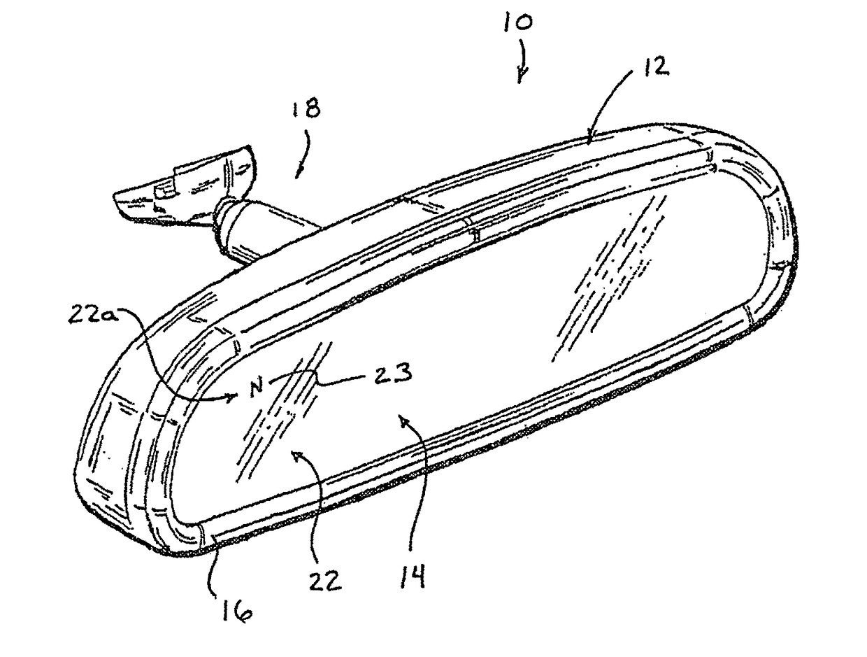
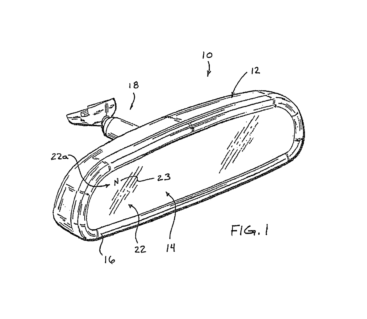
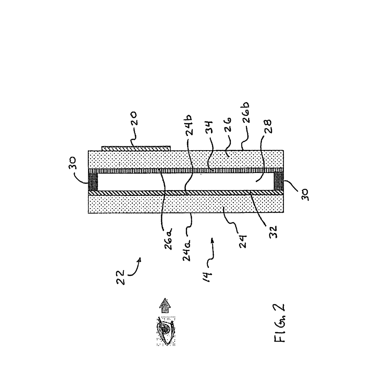
[0052]Referring now to the drawings and the illustrative embodiments depicted therein, an interior rearview mirror assembly 10 for a vehicle includes a mirror casing or housing or shroud or cap or holder 12, a reflective element 14 positioned at a front portion of the mirror casing 12 and a bezel or front casing portion 16 disposed around a periphery of the reflective element. Mirror assembly 10 is adjustably mounted to an interior portion of a vehicle (such as to an interior surface of a vehicle windshield or a headliner of a vehicle or the like) via a mounting structure or mounting configuration or assembly 18. The mirror assembly 10 includes a display device 20 (FIG. 2) that is disposed behind the reflective element 14 and that is operable to display information at a display region 22 of the reflective element for viewing the displayed information through the reflective element by the driver of the vehicle. The display device 20 is operable to display a compass heading or directi...
PUM
Abstract
An interior rearview mirror assembly for a vehicle includes a mirror reflective element and a video display device operable to display video information that is viewable by a driver of the vehicle through said mirror reflective element and at a display region of said mirror reflective element. The video display device may be operable to display a directional heading at a compass display portion of the display region, and means may be provided to adjust the directional heading display to limit image sticking of the displayed directional heading. The mirror assembly may have a touch zone having at least one touch pad established at a perimeter border band of the reflective element, and may have another touch sensor to detect a touch of a user away from the touch zone to determine when a detected touch at the touch zone is an unintentional touch.
Description
CROSS REFERENCE TO RELATED APPLICATIONS[0001]The present application is a 371 national phase entry of PCT Application No. PCT / US2011 / 056295, filed Oct. 14, 2011, which claims the filing benefits of U.S. provisional applications, Ser. No. 61 / 490,375, filed May 26, 2011; Ser. No. 61 / 452,789, filed Mar. 15, 2011; Ser. No. 61 / 449,364, filed Mar. 4, 2011; Ser. No. 61 / 448,916, filed Mar. 3, 2011; Ser. No. 61 / 409,346, filed Nov. 2, 2010, and Ser. No. 61 / 393,407, filed Oct. 15, 2010, which are all hereby incorporated herein by reference in their entireties.FIELD OF THE INVENTION[0002]The present invention relates generally to the field of interior rearview mirror assemblies for vehicles and, more particularly, to an interior rearview mirror assembly that has a compass directional heading display.BACKGROUND OF THE INVENTION[0003]Image sticking is a phenomenon that can occur with a video display and can result in a faint, visible retained image of a persistently displayed image on the video d...
Claims
Application Information
Patent Timeline
Application Date:The date an application was filed.
Publication Date:The date a patent or application was officially published.
First Publication Date:The earliest publication date of a patent with the same application number.
Issue Date:Publication date of the patent grant document.
PCT Entry Date:The Entry date of PCT National Phase.
Estimated Expiry Date:The statutory expiry date of a patent right according to the Patent Law, and it is the longest term of protection that the patent right can achieve without the termination of the patent right due to other reasons(Term extension factor has been taken into account ).
Invalid Date:Actual expiry date is based on effective date or publication date of legal transaction data of invalid patent.

