Ocular fundus auto imager

a technology of ocular fundus and auto imager, which is applied in the field of ocular imaging, can solve the problems of pupils constricting to a size too small to obtain good images, and achieving the effects of enhancing the visibility of certain fundus features, reducing the difficulty of using existing fundus cameras, and reducing the cost of us

Inactive Publication Date: 2006-04-11
VISUAL PATHWAYS
View PDF68 Cites 44 Cited by
  • Summary
  • Abstract
  • Description
  • Claims
  • Application Information

AI Technical Summary

Benefits of technology

[0010]The present invention is in the nature of a fundus camera which automatically and quickly performs all the aligning and focusing functions. As a result, any unskilled person can learn to obtain high quality images after only a few minutes of training and the entire imaging procedure requires far less time than existing fundus cameras. Moreover, all of the automatic aligning and focusing procedures are performed using barely visible infrared illumination. With such illumination, the patient's pupils do not constrict and for all but patients with unusually small natural pupils, no artificial dilation is required. The fundus images can be obtained under infrared illumination and are acceptable for many purposes so that the patient need not be subjected to the extremely bright flashes required for existing fundus cameras. To obtain standard color images using the present invention, it is sometimes necessary to illuminate the eye with flashes of visible light. However, such images can be obtained in a time appreciably shorter than the reaction time of the pupil, so that the pupil constriction that results from the visible flash does not interfere with image collection. Unlike existing fundus cameras, the present invention provides for automatic selection of arbitrary wavelengths of the illuminating light. This facility has two significant advantages. First, it is possible to select illuminating wavelengths that enhance the visibility of certain fundus features. For example, certain near-infrared wavelengths render the early stages of macular degeneration more visible than under white illumination. Second, by careful selection of two or more wavelengths in the near infrared, it is possible to obtain a set of images which, when properly processed, generate a full color fundus image that appears very similar to a color image obtained with white light. Thus, it is possible to obtain acceptable color fundus images without subjecting the patient to bright flashes.
[0011]It is therefore a primary object of the present invention to provide a fundus imager which automatically positions fundus illuminating radiation to enter the pupil while preventing reflection from the cornea from obscuring the fundus image, irrespective of movement of the eye or the patient's head within the head restraint.
[0012]Another object of the present invention is to provide automatic focusing of the fundus image based upon the image itself.

Problems solved by technology

However, to use existing fundus cameras successfully is a very difficult undertaking.
Therefore, the use of existing fundus cameras requires a significant amount of training and skill; even the most skilled operators often collect a large number of images of a single eye in order to select one that is of good quality.
Such illumination would normally cause the pupils to constrict to a size too small to obtain good images.

Method used


Image

  • Ocular fundus auto imager
  • Ocular fundus auto imager
  • Ocular fundus auto imager

Examples


Embodiment Construction

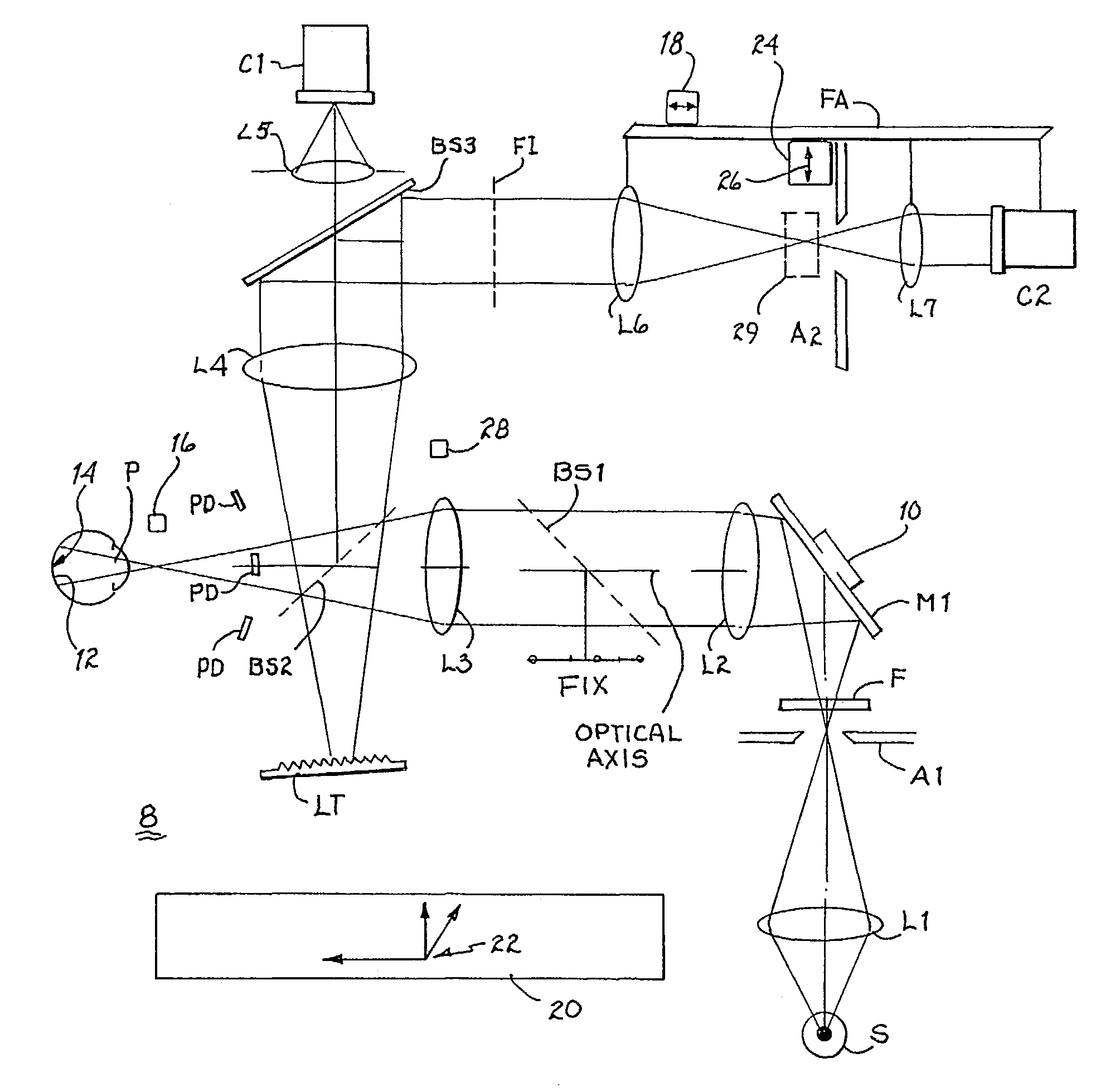
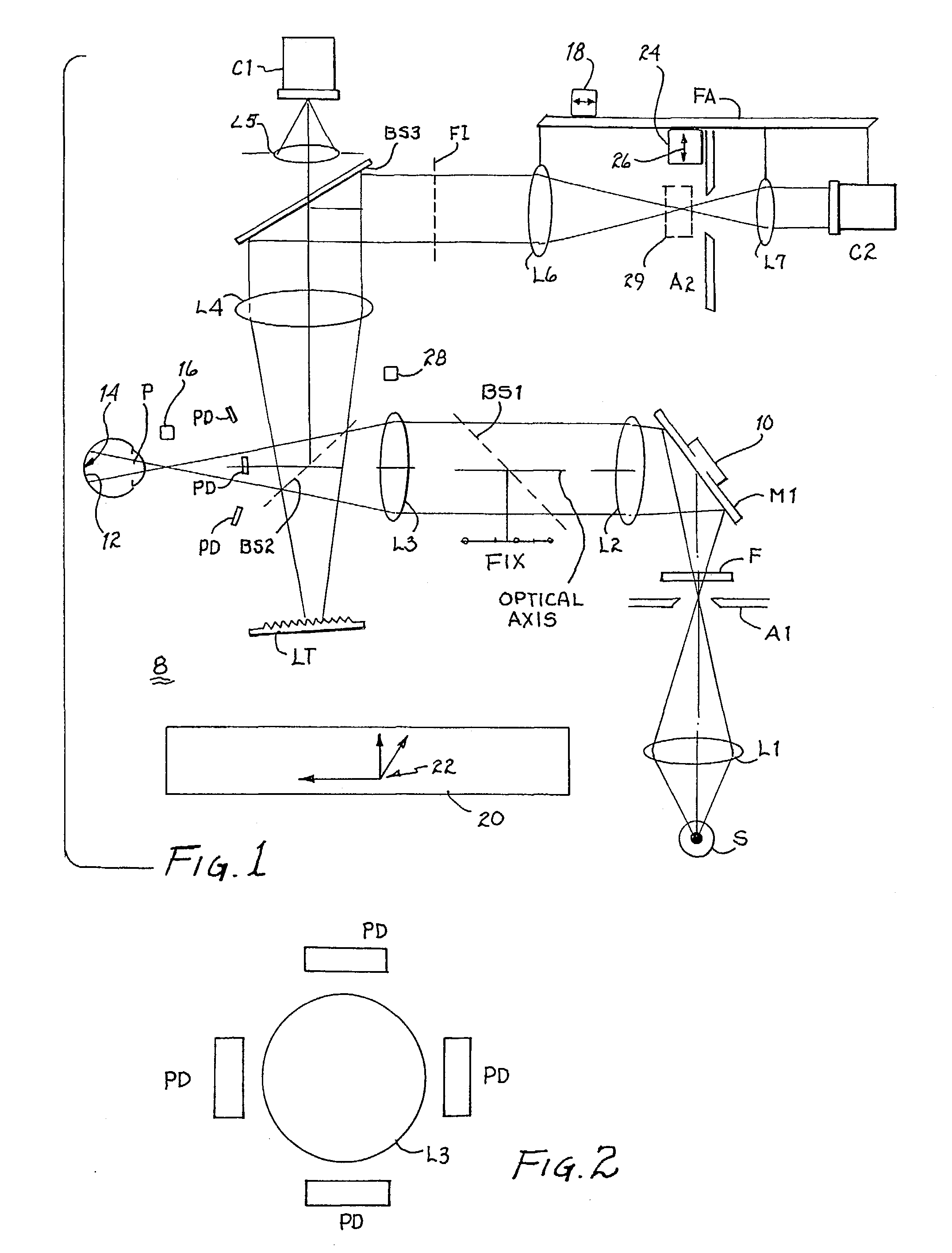
[0041]Referring to FIG. 1, there is illustrated a preferred embodiment of optical system 8 of the present invention. Lens L1 focuses light from a light source S onto a small aperture A1. The light source may be a source of visible light, infrared radiation or of a wavelength in the near visible infrared region. Light passing through aperture A1 passes through a filter F and is reflected by mirror M1 toward lens L2. Mirror M1 is pivotally mounted to permit rotation about two orthogonal axes, which pivotal mounting is represented by device 10 attached to the mirror. Lens L2 collimates (makes parallel) light from aperture A1. A beam splitter BS1 transmits about ninety percent (90%) of the incident light from lens L2 to lens L3. Half of the light passing through lens L3 is reflected by beam splitter BS2 and is absorbed by light trap LT. The other half of the light passing through lens L3 forms an image of aperture A1 in the focal plane of lens L3, which focal plane lies in the plane of ...


PUM


Abstract

An ocular fundus imager (8) automatically aligns fundus illuminating rays to enter the pupil (P) and to prevent corneal reflections from obscuring the fundus image produced. Focusing the produced fundus image is automatically performed and is based upon the fundus image iself. A head restraint for the patient undergoing examination is in the form of a pair of spectacles which is not only easy to use accurately but significantly reduce the gross alignment between the optical system (8) and the patent's pupil (P).

Description

CROSS REFERENCE TO RELATED APPLICATIONS[0001]The present application claims priority to the subject matter disclosed in a provisional application entitled “FUNDUS AUTO IMAGER”, filed Jul. 17, 2000 and assigned Ser. No. 60 / 218,757 directed to an invention made by the present inventor. This application is a continuation-in-part of application Ser. No. 09 / 649,462, filed Aug. 25, 2000, now U.S. Pat. No. 6,296,358, which claims priority from provisional Application No. 60 / 218,757, filed Jul. 17, 2000.BACKGROUND OF THE INVENTION[0002]1. Field of the Invention[0003]The present invention relates to the field of ocular imaging, and, more particularly, to devices for imaging the ocular fundus.[0004]2. Description of Related Art[0005]The term ocular fundus refers to the inside back surface of the eye containing the retina, blood vessels, nerve fibers, and other structures. The appearance of the fundus is affected by a wide variety of pathologies, both ocular and systemic, such as glaucoma, mac...

Claims


Application Information

Patent Timeline
Patent Type & Authority Patents(United States)
IPC IPC(8): A61B3/14A61B3/10A61B3/12A61B3/15
CPCA61B3/152A61B3/156
Inventor CORNSWEET, TOM N.BUCK, GARY F.
Owner VISUAL PATHWAYS
Why Eureka
Try Eureka