Apparatus for inputting biometrical feature

a biometric and feature-based technology, applied in the field of biometrical feature-based inputting apparatus, can solve the problems of wide overlap between the partial images adjacent to each other, the distortion of the image, and the spoofing of personal information in the transaction on the network, so as to improve the precision of the image of the entire finger, prevent the image from being distorted, and image stably

Inactive Publication Date: 2009-03-19
NEC CORP
View PDF8 Cites 38 Cited by
  • Summary
  • Abstract
  • Description
  • Claims
  • Application Information

AI Technical Summary

Benefits of technology

[0029]In the present invention, during the relative motion in which the finger and the 1-dimensional or quasi 1-dimensional image sensor are slid, as well as the finger sliding guide prevents a contact between the finger and the effective pixel unit of the image sensor, a distance between them is kept substantially constant, which prevents an image from being unclear because of the excessively long distance between the finger and the effective pixel unit or prevents the image from being distorted because of a variation in the distance. Also, the emission light that is emitted from the skin surface of the finger after being scattered inside the finger can be stably imaged by the image sensor during the relative motion. Moreover, it is possible to improve the precision of the image of the entire finger that is generated by linking the imaged 1-dimensional or quasi 1-dimensional partial images.

Problems solved by technology

In recent years, in accompaniment with advancement of an information system, the leakage of personal information and the spoofing of a different person in a transaction on a network have become problematic.
However, this conventional fingerprint input apparatus uses an optical part that is expensive and large, which disturbed the miniaturization and lower price of the apparatus.
However, in this method, as shown in FIGS. 3A and 3B, when the finger is slowly moved with respect to the imaging speed of a sensor, the overlap becomes wide between the partial images adjacent to each other, and the judgment of the similarity becomes difficult.
In this way, this conventional example has a problem in which the fingerprint authentication, namely, the authentication based on the biometrical feature is hard to attain, if dermatitis cause the skin to be partially peeled, in addition to the foregoing problems.
Also, because of the non-contact, it is difficult to receive the influence of the state change on the skin surface such as a wet or dry state.
However, in case of the fingerprint detecting apparatus described in Japanese Laid Open Patent Application (JP-P2003-85538A), unless a space is provided between the finger and an image forming system so as to accomplish the non-contact between them, an intended image cannot be obtained.
Also, a frame for fixing the finger is required from the necessity of adjusting a focus, which disturbs the operability and the miniaturization of the apparatus.
For this reason, the fingerprint image of excellent contrast cannot be obtained in the portion in which the skin is actually stripped, because of an adverse influence to the image forming system due to the separation,
However, this requires the large 2-dimensional image sensor, and although an optical system such as a lens is removed, the further miniaturization and lower price of the apparatus are obstructed.
However, when the refractive index of the transparent cover existing between the fingerprint and the 2-dimensional image sensor provided closely thereto is selected to increase the contrast between the bright region corresponding to the convex section of the fingerprint in contact with the transparent cover and the dark region corresponding to the concave that is not in contact, as described in Japanese Laid Open Patent Application (JP-P 2003-006627A), the influence of the reflection and refraction on the boundary becomes strong so that a light component reflecting the skin structure becomes small, As a result, it is difficult to obtain the contrast of the fingerprint image which reflects the skin structure originally appearing in the portion in which the skin is stripped.
This problem is especially severe when a dynamic range of the image sensor cannot be widely set.
However, it is impossible to keep the non-contact state in a constant distance from the finger having a curvature to the 2-dimensional image sensor, and it is also difficult to obtain the stable fingerprint image.
However, the effective information amount of the blood vessel pattern is typically smaller than those of various fingerprints, and this is changed due to any trouble such as a nutrition state, a blood clot, and a blood pressure.
Also, similarly to the proposal (Japanese Laid Open Patent Application (JP-P2003-85538A)) of the non-contact fingerprint detection apparatus, a space is required between the fingerprint and the image forming system, and a frame for fixing the finger is required from the necessity of adjusting the focus, which obstructs the operability and the miniaturization of the apparatus.
Also, only a capillary vessel exists in a fingertip, and the pattern of the capillary vessel cannot be read by the foregoing method.

Method used


Image

  • Apparatus for inputting biometrical feature
  • Apparatus for inputting biometrical feature
  • Apparatus for inputting biometrical feature

Examples


first embodiment

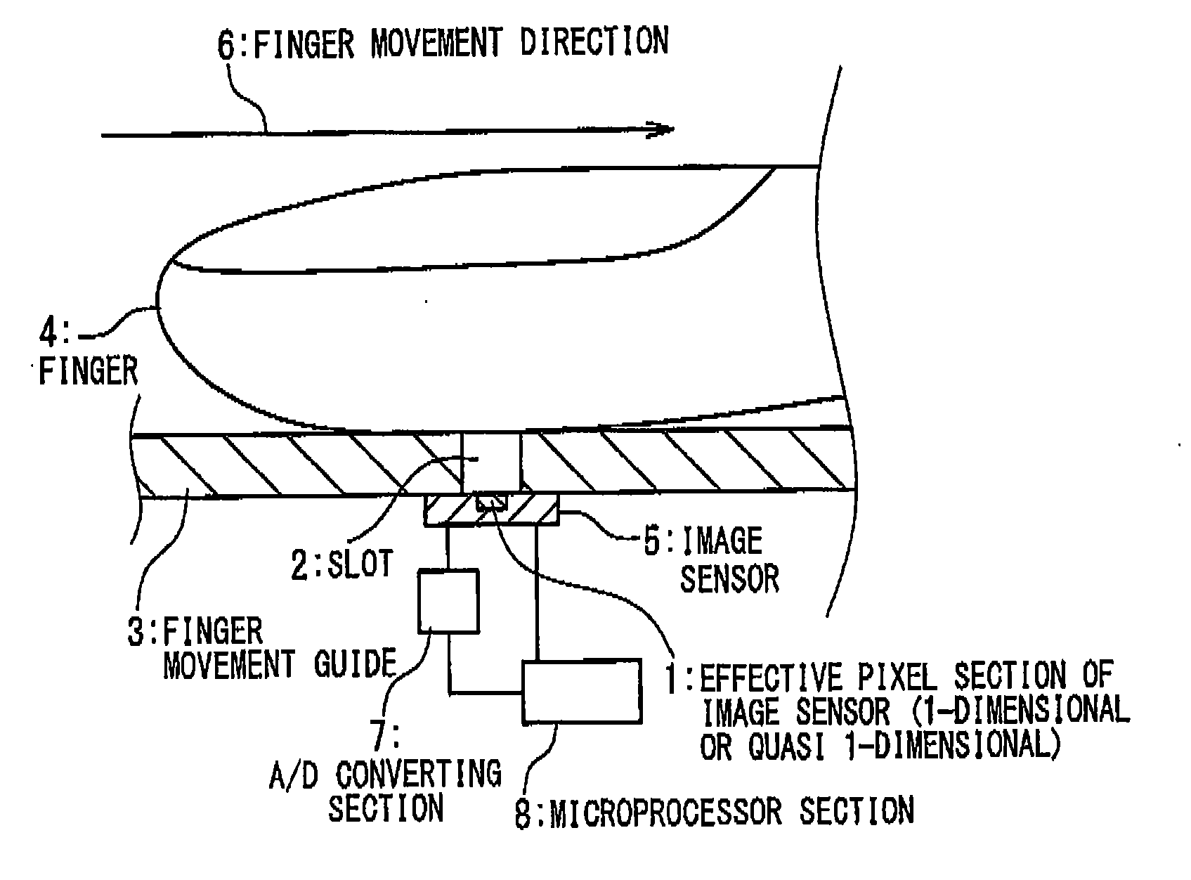
[0057]FIGS. 5A and 5B are views showing the biometrical feature inputting apparatus according to the first embodiment of the present invention. With reference to FIGS. 5A and 5B, the biometrical feature inputting apparatus according to the first embodiment includes a 1-dimensional or quasi 1-dimensional image sensor 5, a finger sliding guide 3 provided in such a manner that a gap 2 is located immediately above an effective pixel unit 1 on this image sensor 5, an A / D converter 7 for converting an analog output signal of the image sensor 5 into a digital signal, and a microprocessor 8 for controlling the imaging (operation) timing of the image sensor 5 and performing an imaging process on the digital signal outputted from the A / D converter 7.

[0058]The 1-dimensional image sensor 5 is an image sensor for one line, and the quasi 1-dimensional image sensor 5 is a rectangular image sensor of about 2 to 20 lines. When a ridge section interval in the fingerprint pattern is about 0.2 to 0.5 m...

second embodiment

[0067]With reference to FIGS. 10A and 10B, the biometrical feature inputting apparatus according to the second embodiment of the present invention differs from the first embodiment shown in FIGS. 5A and 5B, in that a light source of a plurality of light emitting devices is placed on the finger sliding guide 3, and the configurations other than it are same as those of the first embodiment.

[0068]The light emitting devices of the light source 151 are arranged in one line along the long side near the gap 2 of the finger sliding guide 3. When the finger 4 moving in the direction shown by the arrow 6 on the finger sliding guide 3 to image the fingerprint pattern, the finger 4 is illuminated from its finger cushion side (the side of the finger sliding guide 3), to generate the scattered light inside the finger. The reason why the light emitting devices are arrayed on the side on which the finger 4 is pulled with respect to the gap 2 as a center is to make it possible to sufficiently genera...

third embodiment

[0073]With reference to FIG. 14, the biometrical feature inputting apparatus according to the third embodiment of the present invention differs from the first embodiment shown in FIG. 1, in that a protection cover 801 made of optically transmissible solid is inserted into the gap 2 of the finger sliding guide 3, and the components other than it are same as those of the first embodiment.

[0074]The bottom plane of the protection cover 801 is in substantial contact with the effective pixel unit 1 of the image sensor 5, and its top plane is the substantially same plane as the top plane of the finger sliding guide 3. Thus, in order to read the fingerprint pattern of the finger 4, when the vicinity of the first knuckle of the finger 4 is put near the protection cover 801 embedded in the gap 2 of the finger sliding guide 3 and then the finger 4 is pulled so as to trace the protection cover 801, a part of the skin of the finger 4 is always in contact with the protection cover. Thus, among th...


PUM


Abstract

A biometrical feature inputting apparatus includes a 1-dimensional or quasi 1-dimensional image sensor. When a finger and the image sensor are relatively slid, a finger sliding guide keeps a finger and an effective pixel unit of the image sensor to a constant distance without any contact between them. An image processing section sequentially generates partial images by imaging emission light that is scattered inside the finger and then emitted from a skin surface of the finger by the image sensor during the relative motion of the finger and the image sensor and link the partial images to an image.

Description

TECHNICAL FIELD[0001]The present invention relates to a biometrical feature inputting apparatus to authenticate a person.BACKGROUND ART[0002]In recent years, in accompaniment with advancement of an information system, the leakage of personal information and the spoofing of a different person in a transaction on a network have become problematic. In order to prevent these problems, an apparatus is developed that inputs features peculiar to a person and authenticates the person. Also, a smaller size and lower price of an information processing apparatus represented by a mobile phone has been advanced, and a biometrical feature inputting apparatus is also required to be miniaturized and cheapened. Moreover, the personal authentication based on the biometrical features is used for settlement of transaction by use of a credit card.[0003]For this reason, a higher precision of the biometrical feature input apparatus is required more and more, in order to surely authenticate the person unde...

Claims


Application Information

Patent Timeline
Patent Type & Authority Applications(United States)
IPC IPC(8): G06K9/00
CPCA61B5/1172G06K9/00026G06K9/00006G06V40/12G06V40/1335G06T1/00A61B5/117G06F18/00
Inventor HIGUCHI, TERUYUKI
Owner NEC CORP
Why Eureka
Try Eureka