Solid state gimbal system

a solid-state gimbal and system technology, applied in piezoelectric/electrostrictive/magnetostrictive devices, piezoelectric/electrostriction/magnetostriction machines, electrical equipment, etc., can solve the problems of limiting and faking the translation of any device mounted, mechanically and electrically complex, and inherently complex altitude-azimuth systems

Inactive Publication Date: 2008-12-02
QORTEK
View PDF8 Cites 233 Cited by
  • Summary
  • Abstract
  • Description
  • Claims
  • Application Information

AI Technical Summary

Benefits of technology

[0016]An object of the present invention is to provide a lightweight, low-volume, and mechanically simple gimbal device which provides for the direct rotational drive of a spherical element by curvilinear piezoelectric actuators operating in the shear mode.
[0019]Several advantages are noteworthy. The present invention is scalable for use within many applications, including MEMS. The present invention requires substantially less power than mechanically actuated gimbals. The present invention has substantially less moving parts than mechanically actuated gimbals, thereby providing higher operational reliability. The present invention is lighter and smaller than mechanically actuated gimbals. The present invention enables a large field of view over a wide acceptance angle with higher angular rotation rates and precision than mechanically actuated gimbals.

Problems solved by technology

As such, altitude-azimuth systems are inherently complex, costly, and heavy.
Furthermore, components are susceptible to stiction, fretting, and friction, which limit and frustrate the translation of any device mounted to the gimbal.
While the described approaches accurately steer a beam to within submicron accuracy, both are mechanically and electrically complex, difficult and costly to manufacture, fragile, and unreliable in and / or unsuitable to many applications.

Method used


Image

  • Solid state gimbal system
  • Solid state gimbal system
  • Solid state gimbal system

Examples


Embodiment Construction

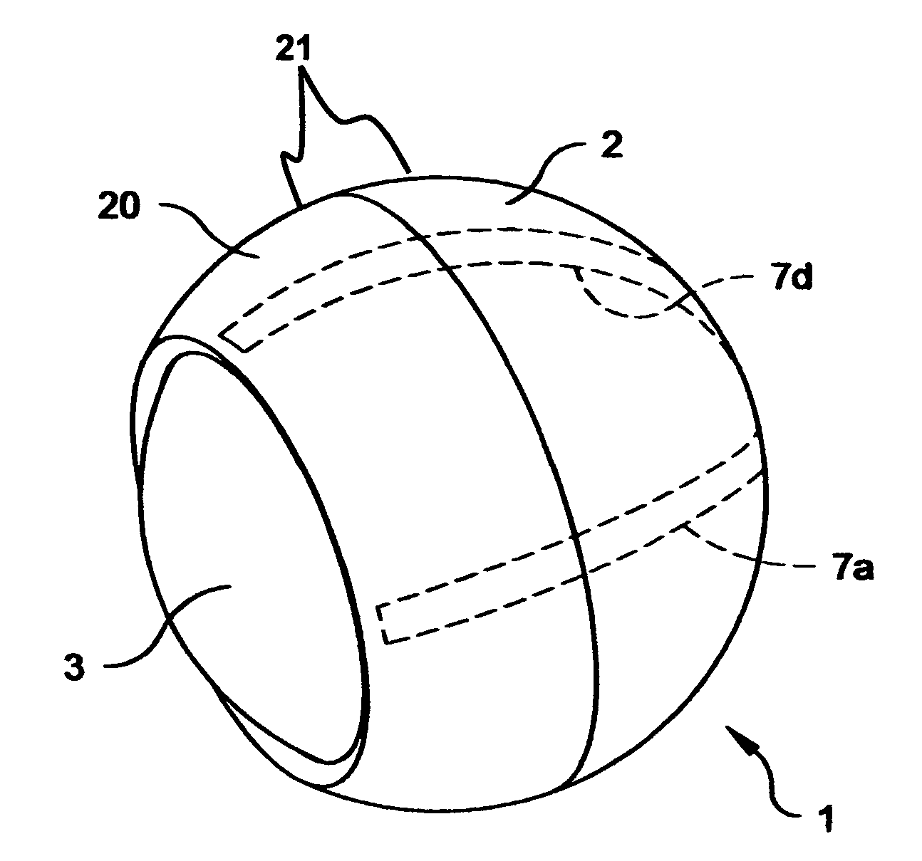
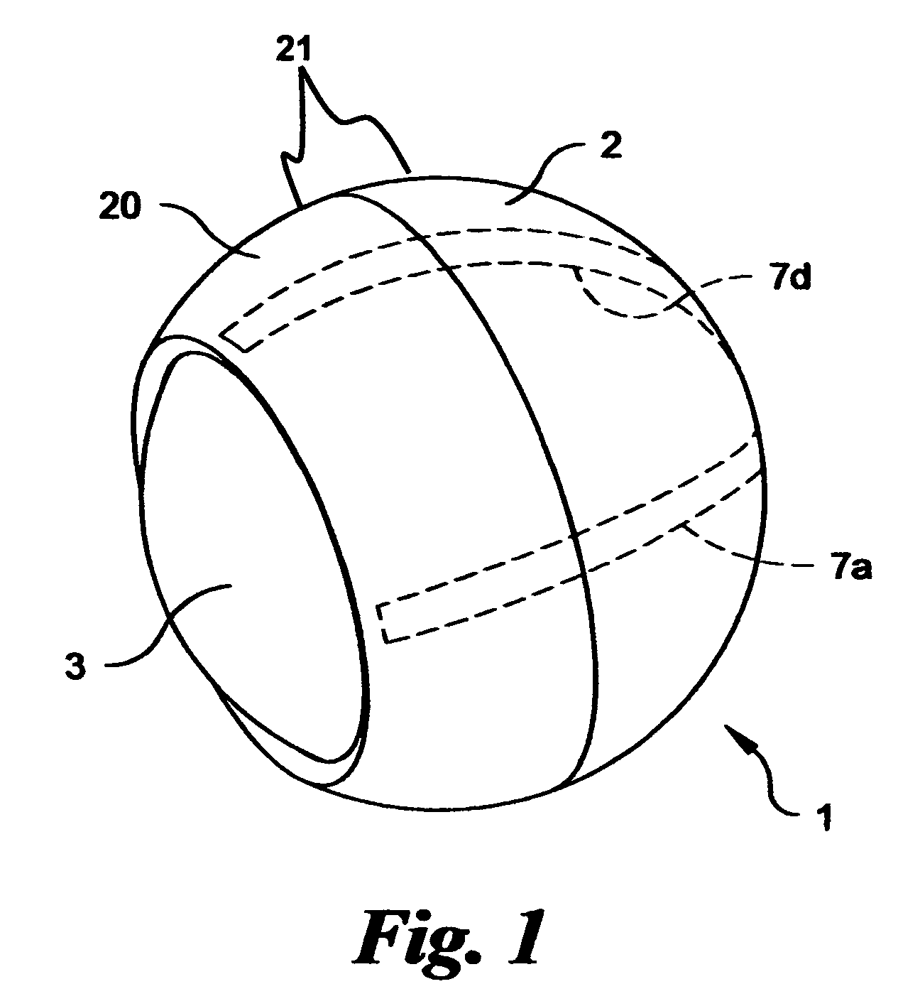
[0034]Referring now to FIG. 1, the gimbal system 1 is shown in a perspective view including a rotatable sphere 3 disposed within a gimbal housing 21, comprising a hemispherical cap 2 and an annular cap 20, with at least two curvilinear actuators 7a, 7d (actuators 7b and 7c not shown) disposed between the rotatable sphere 3 and gimbal housing 21. The rotatable sphere 3 and gimbal housing 21 are dimensioned so as to form a press or compression fit with the curvilinear actuators 7a-7d sufficiently to fix the rotatable sphere 3 in a specific orientation when the curvilinear actuators 7a-7d are electrically inactive. It is also required for the press or compression fit to allow rotation of the rotatable sphere 3 when the curvilinear actuators 7a-7d are activated by an electric field.

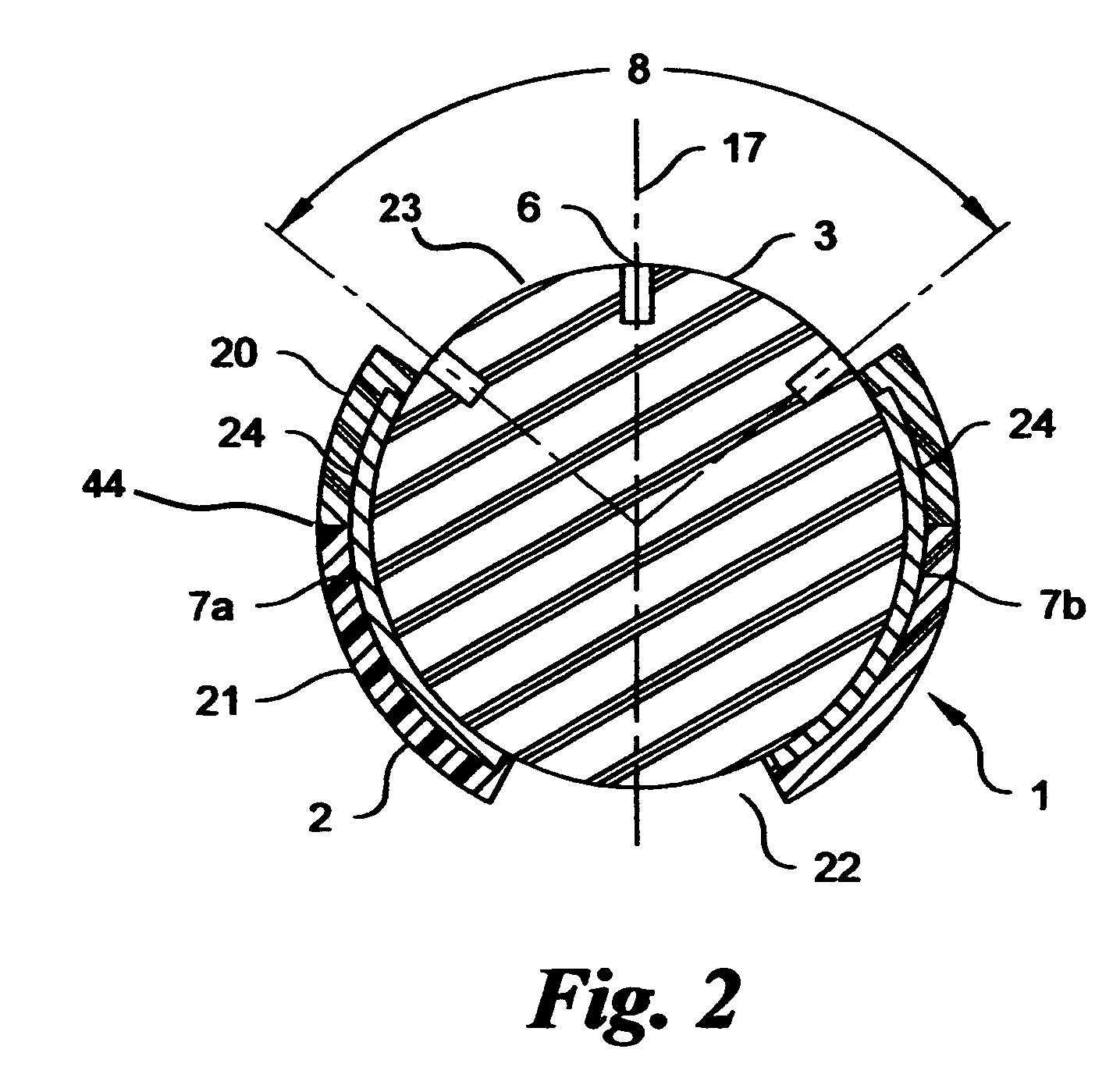
[0035]Referring now to FIGS. 2 and 3, the gimbal system 1 is shown in more detail comprised of a hemispherical cap 2, an annular cap 20, curvilinear actuators 7a-7d, and a rotatable sphere 3. Hemispherical ca...


PUM


Abstract

A non-mechanical gimbal system is presented. The gimbal system includes a gimbal housing, including hemispherical and annular caps, rotatable sphere, and at least two curvilinear actuators. The hemispherical cap is attached to the annular cap in a removable fashion so as to surround the rotatable sphere. The curvilinear actuators are disposed between the rotatable sphere and gimbal housing. Curvilinear actuators rotate the rotatable sphere, via shear induced motion, with respect to the interior surface of the gimbal housing. The present invention has immediate applicability within security devices, games, toys, weapons (including guidance systems and aiming), and communication systems.

Description

CROSS REFERENCE TO RELATED APPLICATIONS[0001]This application is based upon and claims priority under 35 U.S.C. § 119(e) from U.S. Provisional Application No. 60 / 692,938 filed Jun. 22, 2005, entitled “Solid State Gimbal System”, the contents of which are hereby incorporated in its entirety by reference thereto.FEDERALLY SPONSORED RESEARCH AND DEVELOPMENT[0002]The invention disclosed herein was supported, at least in part, by a grant from the Defense Advance Research Projects Agency (DARPA) under DARPA Order No. S039-38 issued by the U.S. Army Aviation and Missile Command under Contract No. W31P4Q-05-C-0180. The Government has certain limited rights to at least one form of the invention.BACKGROUND OF THE INVENTION[0003]1. Field of the Invention[0004]The present invention generally relates to a gimbal system. Specifically, the invention is a lightweight, robust gimbal actively controllable via curvilinear piezo-actuators operating in the shear mode which directly contact and rotate a ...

Claims


Application Information

Patent Timeline
Patent Type & Authority Patents(United States)
IPC IPC(8): H01L41/08
CPCH01L41/0993H02N2/108B33Y80/00H10N30/208
Inventor KNOWLES, GARETH J.MULVIHILL, MAUREENUCHINO, KENJISHEA, BRIAN
Owner QORTEK
Why Eureka
Try Eureka