
Electro-optic device incorporating a discrete photovoltaic device and method and apparatus for making same

a photovoltaic device and optical technology, applied in the field of optical devices, can solve the problems of affecting the operation of the device, and drawing power, etc., and achieves the effect of reducing the number of optical devices

Inactive Publication Date: 2002-08-13
GENTEX CORP
View PDF26 Cites 166 Cited by
  • Summary
  • Abstract
  • Description
  • Claims
  • Application Information

AI Technical Summary

Benefits of technology

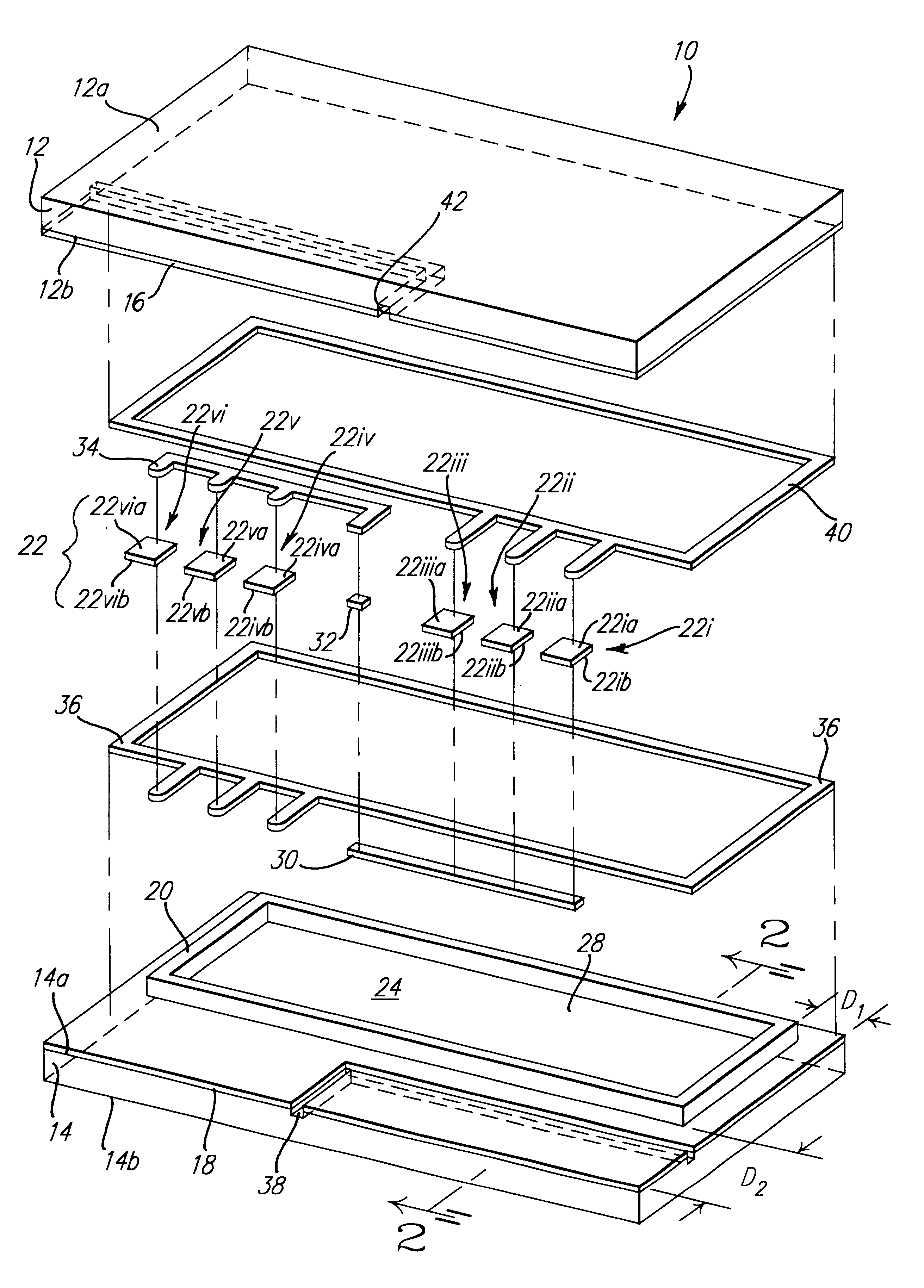
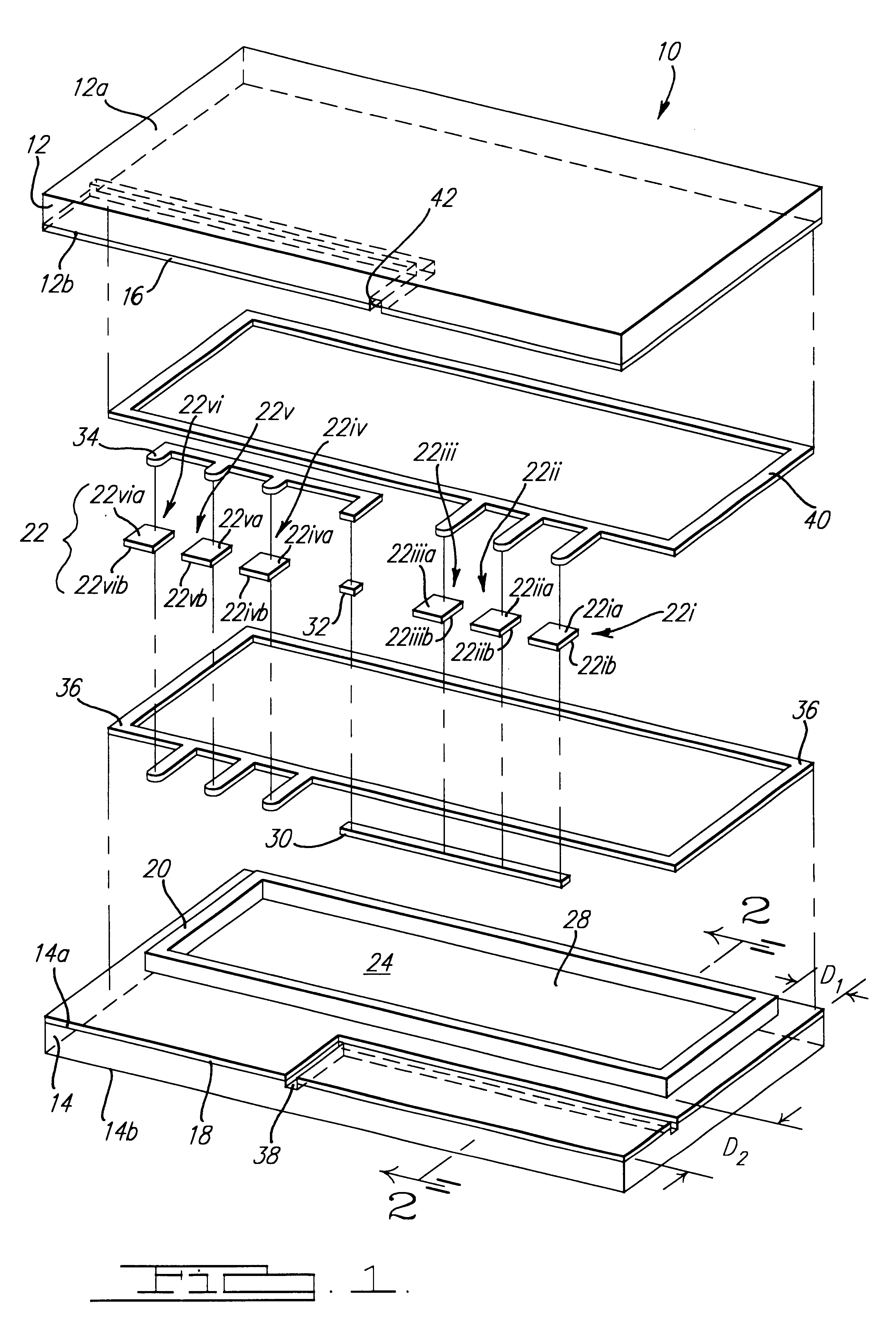
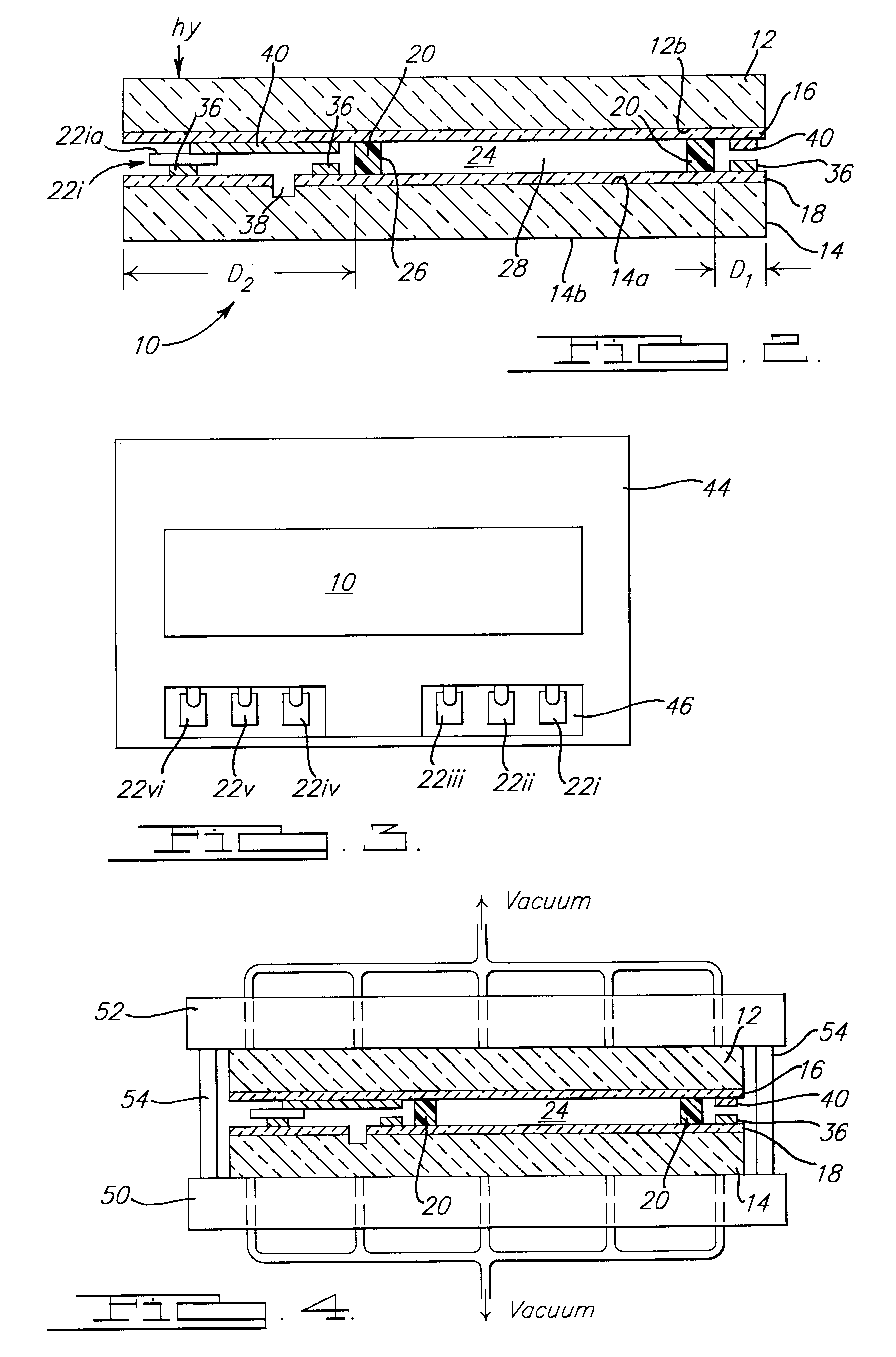
Accordingly, a primary object of the present invention is to provide an improved electro-optic device having a discrete photovoltaic device integrally combined with the electro-optic device where no external drive voltage is needed, no bleaching circuit is required, and no external wiring is necessary.
This is especially important for a photovoltaic-powered device of the present invention. As the sun rises and begins to impinge on the window (and the photovoltaic device), the photovoltaic device generates a current which travels to the two layers of the transparent conductive materials (16 and 18) and a certain electrical potential (P1) is impressed across (and darkens) the electrochromic media 28. When the potential is sufficient for current to flow through an all solution phase electrochromic media 28, the anodic material is continually being oxidized and the cathodic material is being reduced to replace the anodic and cathodic compounds which diffuse away from the transparent conductive layers and spontaneously react to form non-colored species in the bulk of media 28. As the sun continues to rise, more light hits the window and more power is generated by the photovoltaic assembly 22 and impressed on the window, the electrochromic media 28 darkens further. As the sun begins to set, less light hits the window and less power is generated by the photovoltaic assembly 22 and impressed on the window. The transmittance of the electrochromic media 28 spontaneously increases to a new level because the number of species being electrochemically colored is less than before. No other system allows for this simple and accurate auto-adjustment without complicated circuitry.

Problems solved by technology

Thus, incorporating a bleeder resistor complicates the circuitry required for the window system and also draws some power that otherwise could be used in darkening.
Again, solid-state electrochromic devices with good memory, once darkened, will not clear in a reasonable amount of time absent some method of closing the circuit, typically by applying a bleaching potential.
As the degree of colorization of the device increases, the intensity of light impinging on the photovoltaic cells decreases and the output from the photovoltaic cells decreases, creating a limit of how much light the device can block.
When retrofitting electro-optic devices in the configuration of windows it is disadvantageous to have to run wires to each window to supply the external bias.

Method used


Image

  • Electro-optic device incorporating a discrete photovoltaic device and method and apparatus for making same
  • Electro-optic device incorporating a discrete photovoltaic device and method and apparatus for making same
  • Electro-optic device incorporating a discrete photovoltaic device and method and apparatus for making same

Examples


example 2

Propylene carbonate was added to a reaction flask and deoxygenated with dry nitrogen. 20 weight percent of monomers were added to the reaction flask in the molar ratio of 1 part 2-hydroxyethyl methacrylate (HEMA) to 5 parts methyl methacrylate (MMA). The MMA was purified by through distillation at atmospheric pressure using a short neck distillation column. The HEMA was purified by distillation at approximately 3 mm-Hg using a short neck distillation column. The reaction flask was heated to 70 degrees Celsius and a free radical initiator (V-601{Dimethyl 2,2'-Azobis(2-methylpropionate)}(Dimethyl 2,2'-azobisisobutyrate) was added. When the viscosity of the resulting solution increased noticeably, more propylene carbonate (at reaction temperature) was added to the flask. The reaction was continued until completion with the resulting weight percent of the pre-polymer being 10 percent. The pre-polymer solution was diluted to 5% by weight with propylene carbonate. 30 millimolar of Tinuvin...


PUM

PropertyMeasurementUnit
sheet resistanceaaaaaaaaaa
thicknessaaaaaaaaaa
thicknessaaaaaaaaaa

Abstract

Improved electro-optic devices are provided which may be in the configuration of variable transmittance windows, variable transmittance eyeglasses, variable transmittance light filters and displays and other devices wherein the transmittance of light therethrough automatically varies as a function of light impinging thereon. The electro-optic devices include a self-erasing electro-optic medium, and the transmittance of light through such medium varies as a function of electrical signals applied thereto through the agency of at least one photovoltaic cell, enclosed within the electro-optic device, and obviating the necessity of providing external drive voltage or external bleeder resistors or external wiring. In addition, a method and apparatus are provided for making such electro-optic devices.

Description

The present invention relates to electro-optic devices and, more particularly, to electro-optic devices having enclosed therein at least one photovoltaic device.Heretofore, devices of reversibly variable transmittance to electromagnetic radiation have been proposed for such applications as the variable transmittance element in variable transmittance light-filters, variable transmittance eyeglasses, variable reflectance mirrors; and display devices which employ such light-filters or mirrors in conveying information. These variable transmittance light filters have included windows. Among such devices are those where the transmittance is varied by thermochromic, photochromic, or electro-optic (e.g., liquid crystal, dipolar suspension, electrophoretic, electrochromic, etc.) means and where the variable transmittance characteristic affects electromagnetic radiation that is at least partly in the visible spectrum (wavelengths from about 3800 .ANG. to about 7600 .ANG.). Typically, proposed...

Claims


Application Information

Patent Timeline
Patent Type & Authority Patents(United States)
IPC IPC(8): G02F1/01G02F1/13G02F1/133G02F1/153G02F1/163
CPCG02C7/101G02F1/13318G02F1/1533G02F1/163
Inventor BAUER, FREDERICK T.BYKER, HARLAN J.CAMMENGA, DAVID J.GUARR, THOMAS F.POLL, DAVID L.TONAR, WILLIAM L.VANDER ZWAAG, SCOTT W.
Owner GENTEX CORP
Learn More