Reduced profile prosthetic heart valve

a prosthetic heart valve and profile technology, applied in the field of heart valve replacement, can solve the problems of reducing cardiac efficiency, affecting performance, and putting a greater strain on the heart muscle, so as to increase the available space, and reduce the profile of the prosthetic heart valv

Active Publication Date: 2017-07-11
ST JUDE MEDICAL CARDILOGY DIV INC
View PDF298 Cites 53 Cited by
  • Summary
  • Abstract
  • Description
  • Claims
  • Application Information

AI Technical Summary

Benefits of technology

[0008]In one aspect, the present disclosure relates, at least in part, to prosthetic heart valves having features that reduce the profile of the valves and that otherwise increase the available space on the valve for attaching additional features, such as PV leak mitigation features. For example, if a PV leak mitigation (or other) feature is added to a prosthetic heart valve, the profile of the prosthetic valve may increase. However, methods and apparatus disclosed herein may help reduce the profile of the prosthetic valve to partially or completely offset the increase in profile resulting from the addition of additional valve features. A number of other benefits may also be obtained from the disclosure provided herein.

Problems solved by technology

For example, inaccurate deployment and anchoring may result in the leakage of blood between the implanted heart valve and the native valve annulus, commonly referred to as perivalvular or paravalvular leakage (“PV leak”).
In aortic valves, this leakage enables blood to flow from the aorta back into the left ventricle, which can reduce cardiac efficiency and put a greater strain on the heart muscle.
Additionally, calcification of the aortic valve may affect performance and the interaction between the implanted valve and the calcified tissue is believed to be relevant to leakage.
Adding features to a prosthetic heart valve to help mitigate PV leak may result in the profile of the valve increasing in size.
Increasing the profile of the valve may be undesirable, for example, because delivering the valve may require a correspondingly larger delivery device.
Similarly, adding features to a prosthetic valve has a potential of adversely impacting other design factors, such as hemodynamic performance, durability, and sealing.

Method used


Image

  • Reduced profile prosthetic heart valve
  • Reduced profile prosthetic heart valve
  • Reduced profile prosthetic heart valve

Examples


Embodiment Construction

[0032]As used herein, the term “proximal,” when used in connection with a prosthetic heart valve, refers to the end of the heart valve closest to the heart when the heart valve is implanted in a patient, whereas the term “distal,” when used in connection with a prosthetic heart valve, refers to the end of the heart valve farthest from the heart when the heart valve is implanted in a patient. The term “circumferential,” when used in connection with a prosthetic heart valve, refers to the direction around the perimeter of the valve. The term “leading end,” when used in connection with a suture, refers to the end initially advanced through a material, while the term “trailing end” refers to the opposite end.

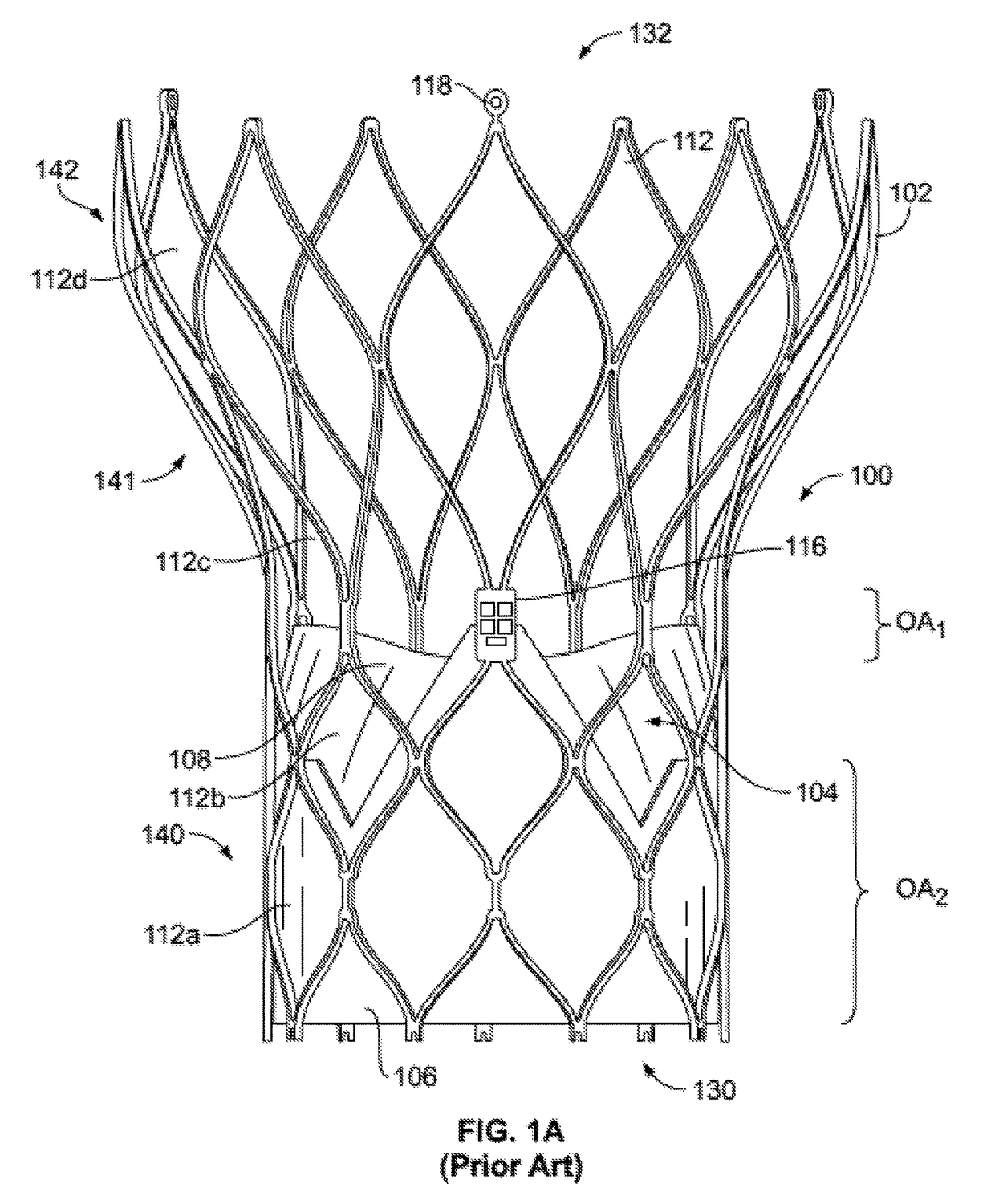
[0033]FIG. 1A shows a collapsible stent-supported prosthetic heart valve 100 known in the art. The prosthetic heart valve 100 is designed to replace the function of a native tricuspid, bicuspid or unicuspid valve of a patient, such as a native aortic valve. It should be noted that w...


PUM


Abstract

A prosthetic heart valve may include a stent body with a plurality of cells arranged in circumferential rows and a cuff attached to the stent. A leaflet attachment panel may be attached to and span a portion of one of the cells. A prosthetic valve element, such as a leaflet having a belly, may be mounted to the leaflet attachment panel. The leaflet attachment panel may not be integral with the stent body. A reduced overlap area may be defined between a proximal end of the stent body and a proximalmost point of attachment of the leaflet belly to the cuff. The reduced overlap area may have a size dependent upon the circumferential row of cells the leaflet attachment panel is attached to and a position of the portion of the leaflet attachment panel to which the leaflet is mounted. Alternately, the leaflet may be attached directly to the stent.

Description

CROSS-REFERENCE TO RELATED APPLICATIONS[0001]The present application claims the benefit of the filing date of U.S. Provisional Patent Application No. 61 / 900,588, filed Nov. 6, 2013, the disclosure of which is hereby incorporated by reference herein.BACKGROUND[0002]The present disclosure relates to heart valve replacement and, in particular, to collapsible prosthetic heart valves. More particularly, the present disclosure relates to collapsible prosthetic heart valves having designs that facilitate the inclusion of additional features, such as paravalvular leak (“PV leak”) mitigation features.[0003]Prosthetic heart valves that are collapsible to a relatively small circumferential size can be delivered into a patient less invasively than valves that are not collapsible. For example, a collapsible valve may be delivered into a patient via a tube-like delivery apparatus such as a catheter, a trocar, a laparoscopic instrument, or the like. This collapsibility can avoid the need for a mor...

Claims


Application Information

Patent Timeline
Patent Type & Authority Patents(United States)
IPC IPC(8): A61F2/24
CPCA61F2/2409A61F2/2412A61F2/2418A61F2220/005A61F2220/0075A61F2250/0008A61F2250/0062
Inventor BRAIDO, PETER N.SMITH, KENT J.
Owner ST JUDE MEDICAL CARDILOGY DIV INC
Why Eureka
Try Eureka