

Stepper motor driver circuit
a technology of stepper motors and driver circuits, applied in the direction of resistance/reactance/impedence, dynamo-electric converter control, instruments, etc., can solve the problems of excessive load on the control unit of the mechanism, noise during the driving and driving efficiency of the stepper motor, and limit the vibration isolation based on the micro-step driving
- Summary
- Abstract
- Description
- Claims
- Application Information
AI Technical Summary
Benefits of technology
Problems solved by technology
Method used
Image



Examples
first embodiment
[0021](First Embodiment)
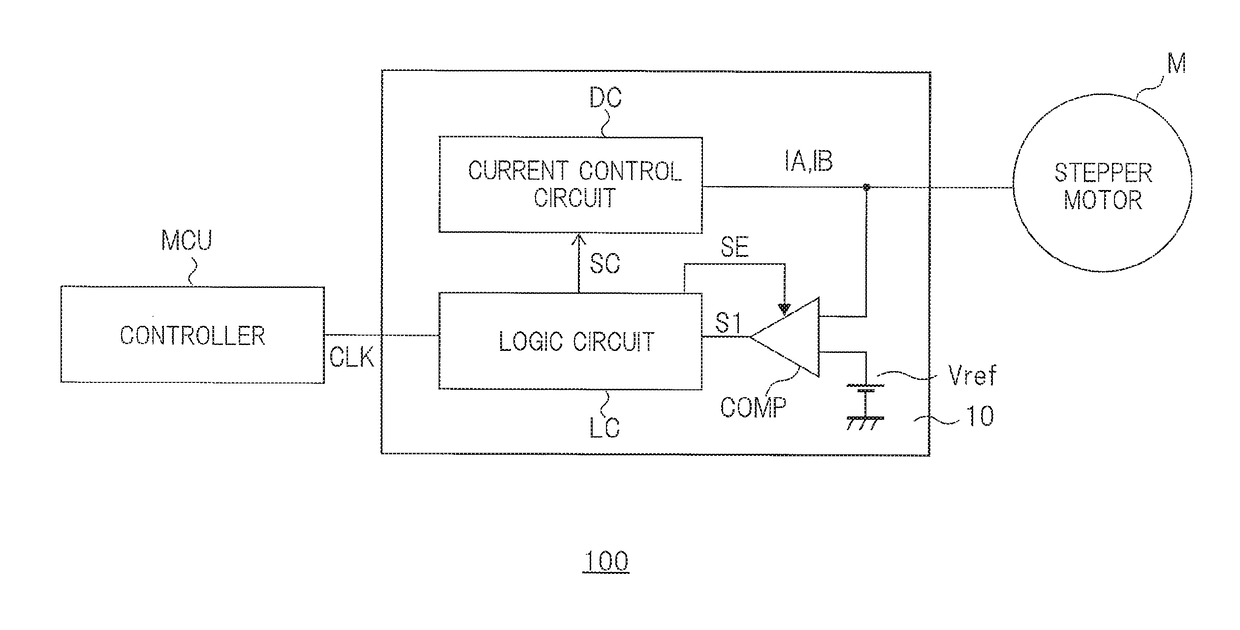
[0022]FIG. 1 is a diagram showing an example of a configuration of a stepper motor driver system 100 including a stepper motor driver circuit 10 according to a first embodiment. FIG. 2 is a waveform diagram showing waveforms of a reference clock signal “CLK”, a driving current having a pseudo-sinusoidal waveform supplied to a coil of a stepper motor “M” and an enable signal “SE”. FIG. 2 shows an example in which a driving current is supplied to coils of two different phases (A phase and B phase). In the example shown in FIG. 2, for the sake of simplicity, only the enable signal “SE” for the driving current of the A phase is shown, and the enable signal “SE” for the driving current of the B phase is not shown. The following description will be focused on a driving current “IA” of the A phase. However, the description of the driving current of the A phase holds true for the driving current of the B phase and other driving currents of different phases.
[0023]As s...
PUM
 Abstract
Description
Claims
Application Information