C-arm of medical imaging system

a medical imaging system and carm technology, applied in the field of carm of medical imaging systems, can solve the problems of running the risk of interfering with the floor of the room where the medical imaging system is located, the highest value of object image distance cannot be used, and the limit of object image distan

Active Publication Date: 2018-01-30
GENERAL ELECTRIC CO
View PDF8 Cites 0 Cited by
  • Summary
  • Abstract
  • Description
  • Claims
  • Application Information

AI Technical Summary

Benefits of technology

[0004]More particularly, an embodiment provides a C-arm which connection between radiation detector support and C-shaped structure presents a limited bulk in all configurations, even when the C-arm rotates. This connection is structured so that it can be bent so that its bulk is reduced as compared to the situation where it is not bent. Reducing bulk means not necessarily reducing the global volume but at least reducing one dimension of the connection, and more particularly reducing a dimension of the connection so that the connection projection beyond the end of the C-shaped structure is reduced compared to the connection projection beyond the end of the C-shaped structure if such dimension had not been reduced.
[0026]In an embodiment, the invention also provides a medical imaging method using medical imaging system according to embodiments of the invention to increase or to decrease the object image distance.

Problems solved by technology

This presents the drawback that, when the C-arm rotates, it will run the risk to interfere with the floor of the room where the medical imaging system stands.
Therefore, when using this prior art, in the configuration where the C-arm rotates, the highest values of object image distance cannot be used.
So this prior art presents the drawback that the object image distance is limited because of the presence of the lift, in the configurations where the C-arm rotates.

Method used


Image

  • C-arm of medical imaging system
  • C-arm of medical imaging system

Examples


Embodiment Construction

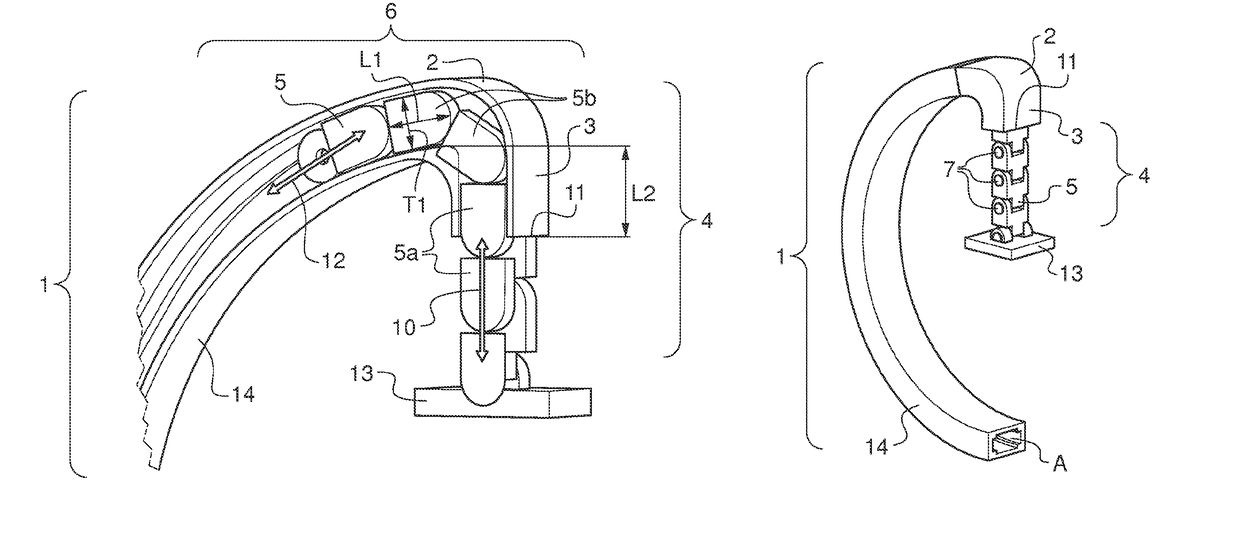
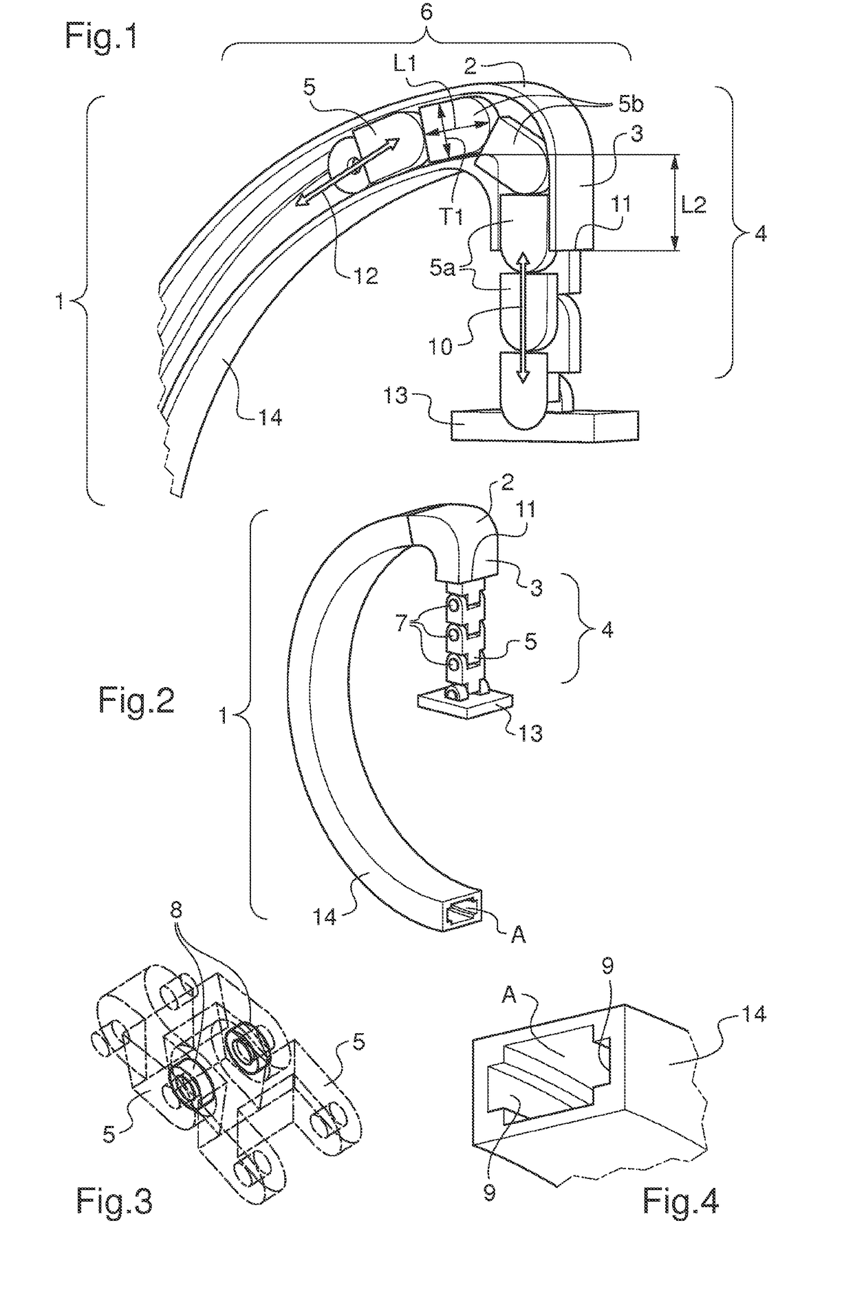
[0032]FIG. 1 shows a cross section view of an example of a C-arm of a medical imaging system according to an embodiment of the invention. The C-arm 1 comprises a C-shaped structure 14 which is hollow. Here the casing where the connection 6 is stored is the hollow C-shaped structure 14. The C-shaped structure 14 is ended by an extension comprising, first a hollow bent portion 2 and then a hollow straight portion 3. The outside opening of the hollow straight portion 3 is the end 11 of the C-shaped structure 14 of the C-arm 1.

[0033]A support 13 is adapted to receive a radiation detector not shown on FIG. 1 for sake of simplicity. The radiation detector is to be fixed under the support 13. A connection 6 comprises a chain 4 and an actuator 12. The actuator 12 is adapted to push the chain 4 to spread it outside the C-shaped structure 14 and to pull the chain 4 to store it inside the C-shaped structure 14, as is shown by the double arrow 12 symbolizing the actuator 12. The chain 4 compris...


PUM


Abstract

A C-arm of a medical imaging system, comprising a C-shaped structure, a radiation detector support and a connection linking said support to said C-shaped structure so that said support can move toward and away from an end of said C-shaped structure, wherein said connection is structured so as to be bendable to reduce its bulk.

Description

FIELD OF THE INVENTION[0001]Embodiments of the present invention relate to a C-arm of a medical imaging system. More particularly, embodiments of the present invention relate to a connection linking a radiation detector support to a C-shaped structure so that the radiation detector support can move toward and away from an end of the C-shaped structure.BACKGROUND OF THE INVENTION[0002]According to a prior art, it is known a rigid, fixed and straight, connection linking radiation detector support to C-shaped structure which moves like a lift. So, this connection and the radiation detector support and the radiation detector, all fixed and integral with one another, move simultaneously upwards and downwards in a rectilinear motion. In this prior art, when the object image distance (OID) in the C-arm is set to maximum, the connection projects, outwards the C-shaped structure, far away beyond the end of the C-shaped structure. This presents the drawback that, when the C-arm rotates, it wi...

Claims


Application Information

Patent Timeline
Patent Type & Authority Patents(United States)
IPC IPC(8): A61B6/00
CPCA61B6/4452A61B6/4441
Inventor GALLONI, BRUNO
Owner GENERAL ELECTRIC CO
Why Eureka
Try Eureka