
Brake system with master cylinder, disengaged from the brake pedal, and hydraulic brake booster

a brake system and master cylinder technology, applied in the direction of braking systems, rotary clutches, fluid couplings, etc., can solve the problems of large size of known systems and complex design, and achieve the effect of simple conditions and assembly

Active Publication Date: 2012-06-07
ROBERT BOSCH GMBH
View PDF2 Cites 2 Cited by
  • Summary
  • Abstract
  • Description
  • Claims
  • Application Information

AI Technical Summary

Benefits of technology

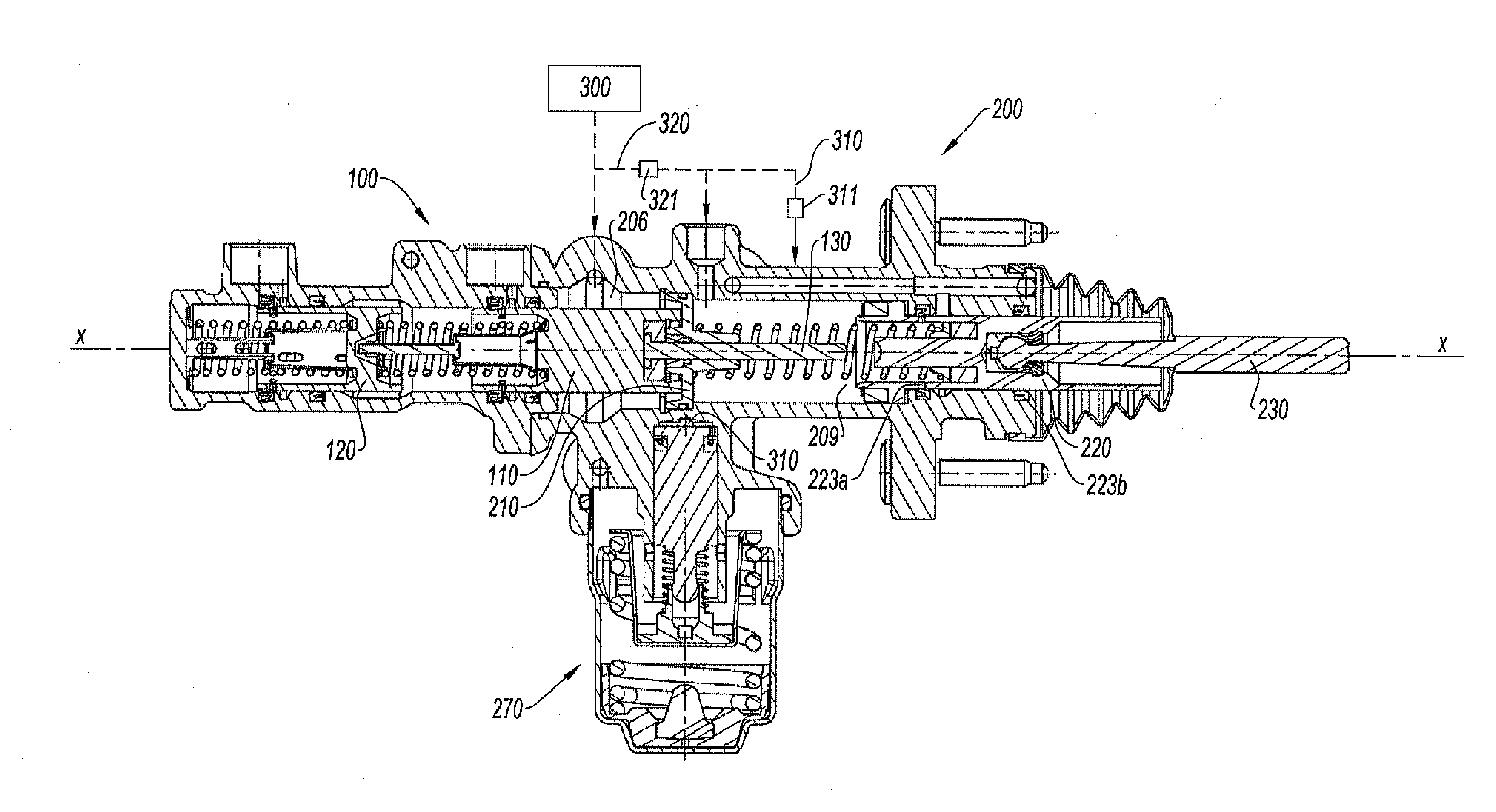
[0011]Said braking system has the advantage of a particularly simple design and of being composed of a smaller number of elements which translates into a significant advantage from the point of view of manufacturing cost. The bulk is reduced which is a very great advantage in terms of the integration of said braking system in the engine compartment of a vehicle.
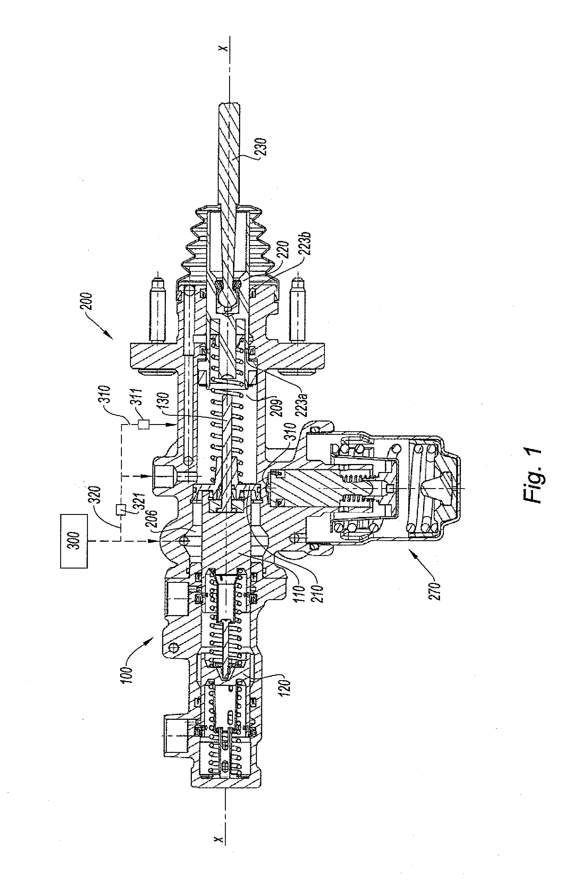
[0014]Thus, the braking system according to the invention makes it possible to pressurize the master cylinder, in particular a tandem master cylinder which is decoupled from the brake pedal. Said pressurization does not require an additional piston for the hydraulic brake booster. The pressurization may be controlled by the brake pedal but also automatically by a control system such as ABS, ARS systems without intervention by the driver and without the driver noticing it by a reaction on the brake pedal. In the event of malfunction of the high pressure unit, it is possible to provide emergency operation, firstly by placing the actuator chamber in communication with the boost chamber to force fluid from the actuator chamber back to the boost chamber as a function of the thrust exerted on the brake pedal and the control rod.
[0016]In the event of first-level hydraulic emergency assistance, the force exerted by the driver on the brake pedal is boosted and, as a function of the relationship of the active sections of the actuating piston and the piston of the master cylinder, this boosting effect is produced by steady force on the brake pedal, without dead travel, since only the actuator chamber is filled with fluid.
[0022]Regarding the assembly, due to the structure of the tandem master cylinder to which the push rod is directly associated and the hydraulic brake booster structure with the separating disc, it is possible to produce the two sub-assemblies separately and to assemble them in very simple conditions.

Problems solved by technology

However, said known systems generally have the drawback of being relatively bulky and their design complex, as disclosed in the patent application US 2006 / 0158026 A1.

Method used


Image

  • Brake system with master cylinder, disengaged from the brake pedal, and hydraulic brake booster
  • Brake system with master cylinder, disengaged from the brake pedal, and hydraulic brake booster
  • Brake system with master cylinder, disengaged from the brake pedal, and hydraulic brake booster

Examples


Embodiment Construction

[0032]FIG. 1 shows a braking system comprising a master cylinder 100 combined with a hydraulic brake booster 200 according to the invention. In this case, the master cylinder 100 is a tandem master cylinder 100. In the conventional manner, the orientation of the braking system, for the purposes of the present description, is the traditional orientation, the master cylinder 100 being located to the left and the brake booster 200 to the right, such that the master cylinder is located at the front of the brake booster and the brake pedal to the rear of the brake booster.

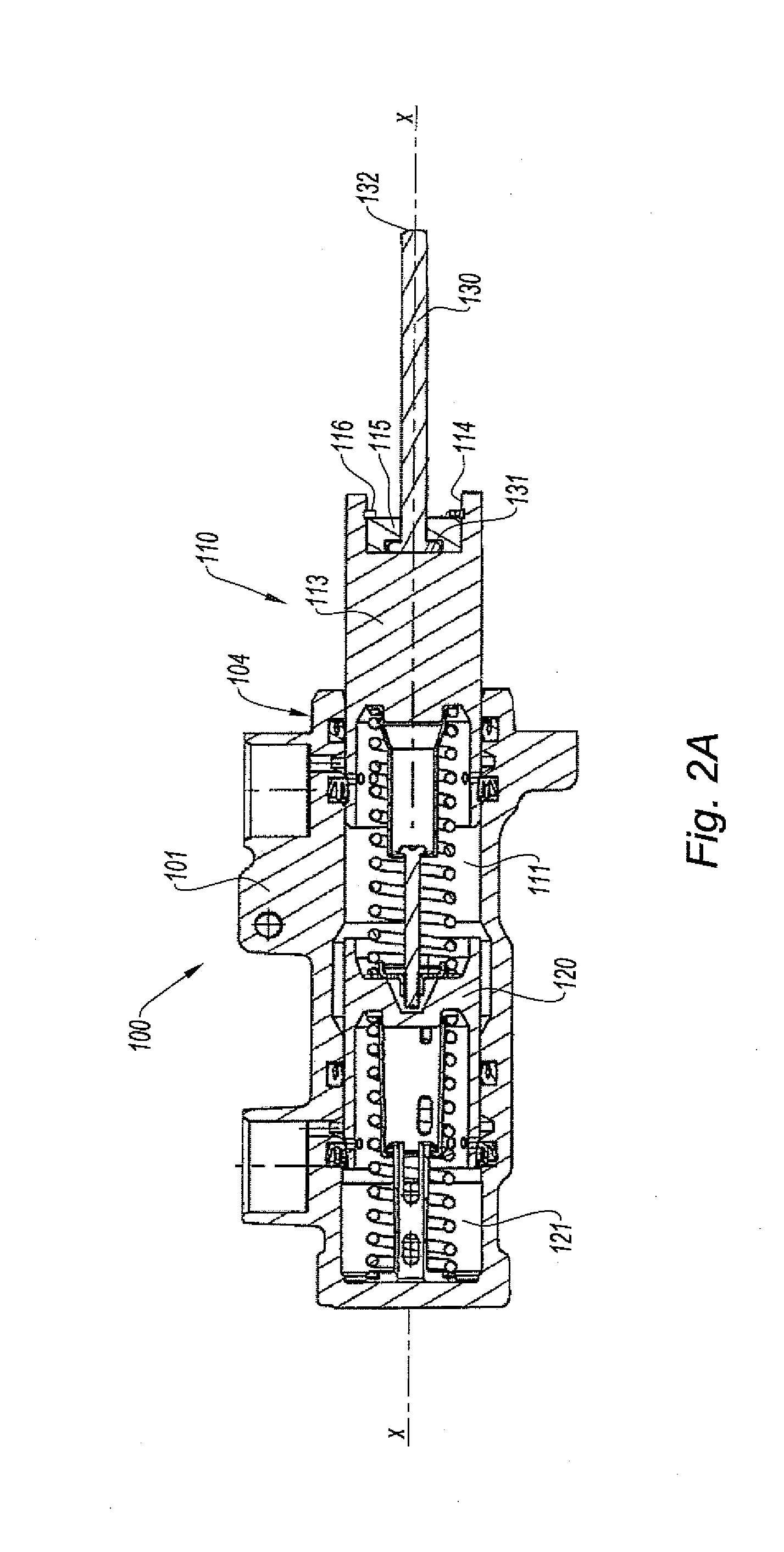
[0033]In more detail according to the sectional views of FIGS. 2A-2D, and in particular FIG. 2A, the tandem master cylinder 100 comprises a body 101 housing a primary piston 110 and a secondary piston 120, each defining a chamber 111, 121 supplied with brake fluid from a reservoir, not shown, via fluid links which are open when the pistons are in the neutral position, and not displaced, and which are closed as soon as t...


PUM


Abstract

Braking system with master cylinder (100), decoupled from the brake pedal and hydraulic brake booster (200), comprisinga boost chamber (206) in which the rear of the piston (110) of the master cylinder (100) is inserted, supplied in a controlled manner by a high-pressure unit (300), supplying brake fluid under high pressure on command to the boost chamber in order to act on the piston (110) of the master cylinder (100), andan actuator chamber (209) receiving an actuator piston (220) connected to the control rod (230) of the brake pedal.A controlled hydraulic link (320, 321) connects the boost chamber (206) and the actuator chamber (209) and a further controlled hydraulic link (310, 311) connects the actuator chamber (209) to the chamber of a brake simulator (270).

Description

BACKGROUND OF THE INVENTION[0001]The present invention relates to a braking system with master cylinder, decoupled from the brake pedal and hydraulic brake booster, comprising[0002]a boost chamber into which the rear of the piston of the master cylinder is inserted, supplied in a controlled manner by a high pressure unit, supplying brake fluid under high pressure on command to the boost chamber in order to act on the piston of the master cylinder,[0003]an actuator chamber receiving an actuator piston connected to the control rod of the brake pedal,[0004]a controlled hydraulic link between the boost chamber and the actuator chamber.[0005]Numerous braking systems exist with a hydraulic brake booster arranged in series with the master cylinder. However, said known systems generally have the drawback of being relatively bulky and their design complex, as disclosed in the patent application US 2006 / 0158026 A1.SUMMARY OF THE INVENTION[0006]The object of the present invention is to develop...

Claims


Application Information

Patent Timeline
IPC IPC(8): B60T13/138
CPCB60T7/042B60T13/145B60T8/441B60T8/4077
Inventor SOKOU, KOMIWINKLER, ROMANCAGNAC, BASTIENANDERSON, CHRISSPROCQ, RAYNALD
Owner ROBERT BOSCH GMBH
Learn More