

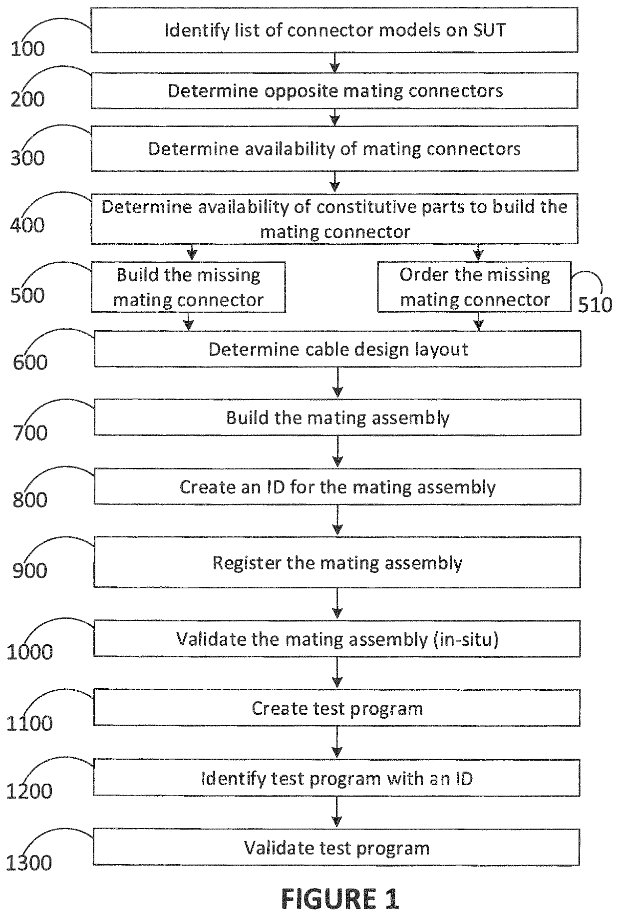
Method for assembling a connectorized equipment
a technology of connectorized equipment and assembly method, which is applied in the direction of contact member assembly/disassembly, lamp testing, contact member case/base manufacture, etc., can solve the problems of limited work scope, unpredictable delays, and limitations in the performance of existing handheld testers and ates
- Summary
- Abstract
- Description
- Claims
- Application Information
AI Technical Summary
Benefits of technology
Problems solved by technology
Method used
Image

Examples
Embodiment Construction
[0095]When, at the beginning of or during a testing of electrical equipment, it is noted that a part of test equipment is faulty, missing or incomplete, there is a need to fulfill this need promptly. The same applies to a part of electrical equipment to be tested, since the inability to repair or replace a faulty part of electrical equipment may have the same effect of delaying the workflow, and postponing the moment when the electrical equipment is put back in service. The electrical equipment may comprise electrical cables, electrical harnesses, electrical components such as relays, coil, control panels and all sorts of parts in a connectorized electrical equipment. The term “connectorized” electrical equipment encompasses electrical equipment which have at least one connector, with wires connected thereto. The connectorized electrical equipment may comprise a mix of parts such as wire harnesses, or pair of connectors with wires connected therebetween, or a connector having wires ...
PUM
| Property | Measurement | Unit |
|---|---|---|
| Electrical tests | aaaaa | aaaaa |
| time | aaaaa | aaaaa |
| dimensions | aaaaa | aaaaa |
Abstract
Description
Claims
Application Information