Turbine assembly support program, turbine assembly support system, and turbine assembly method using corrected finite element model

a turbine and support system technology, applied in the direction of machines/engines, mechanical equipment, instruments, etc., can solve the problems of large bolt size, difficult cooling, and long time required for turbine assembly work, and achieve the effect of high accuracy, assemble and high accuracy

Active Publication Date: 2021-10-19
MITSUBISHI POWER LTD
View PDF11 Cites 0 Cited by
  • Summary
  • Abstract
  • Description
  • Claims
  • Application Information

AI Technical Summary

Benefits of technology

[0007]According to the present invention, it is possible to calculate the deformation amount of the evaluated portion through analysis using a correction model reflecting actual measurement information of a real machine, so that it is possible to evaluate the position adjustment amount of the stationary body with high accuracy, making it possible to assemble a turbine with high accuracy. Further, the casing temporary assembly process is omitted, making it possible to assemble a turbine in a short period of time.

Problems solved by technology

Further, the bolts are large in size and are not easily cooled.
Thus, the process of temporarily assembling the upper half part and the lower half part of the casing requires an enormous amount of labor and time, and, partly due to this temporary assembly process, long time is required for the turbine assembly work.
Further, the actual casing involves variation in the deformation amount at the time of bolt fastening due to individual differences in configuration and material, and it is not always possible to secure the requisite accuracy by evaluation based on actual result data.

Method used


Image

  • Turbine assembly support program, turbine assembly support system, and turbine assembly method using corrected finite element model
  • Turbine assembly support program, turbine assembly support system, and turbine assembly method using corrected finite element model
  • Turbine assembly support program, turbine assembly support system, and turbine assembly method using corrected finite element model

Examples


Embodiment Construction

[0022]In the following, an embodiment of the present invention will be described with reference to the drawings.

(Turbine)

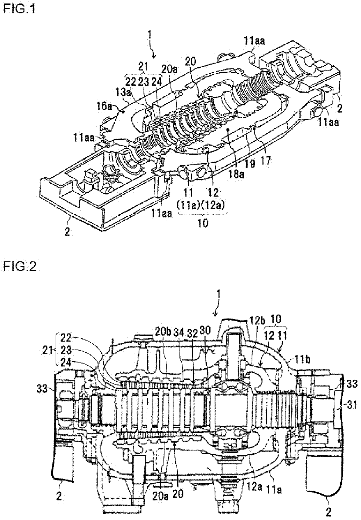
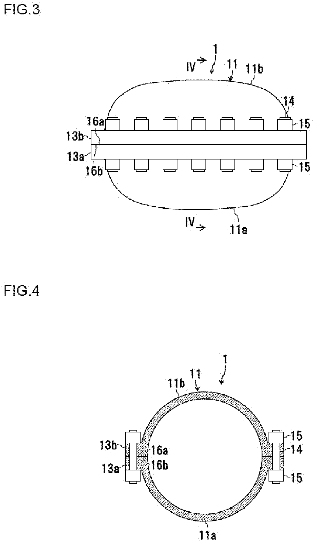
[0023]FIG. 1 is a perspective view illustrating a structure of a lower half part of a steam turbine constituting an application example of the present invention. FIG. 2 is a schematic sectional view of a complete assembly product of the steam turbine shown in FIG. 1 taken along a vertical plane including a turbine center axis, FIG. 3 is a schematic external side view illustrating the casing of the steam turbine shown in FIG. 2, and FIG. 4 is a sectional view taken along arrow line IV-IV of FIG. 3. While the present embodiment will be described as applied to a steam turbine, the present invention is also applicable to the assembly work of a gas turbine (including one-axis type and two-axis type). As the main components, a steam turbine 1 shown is equipped with a casing 10, a stationary body 20, and a rotary body 30 (FIG. 2).

(Casing)

[0024]The casing 10 is a casing c...


PUM


Abstract

In assembling a turbine including: a casing consisting of an upper half part and a lower half part fastened together by bolts; a stationary body accommodated in the casing and supported by the lower half part; and a rotary body supported by a plurality of bearings so as to be situated on the inner side of the stationary body, there are executed: a procedure of reading a finite element model of the three-dimensional configuration of the turbine; a reading procedure of reading actual measurement information on the three-dimensional configuration of the upper half part and the lower half part of the casing in the open state; a model correction procedure of reflecting actual measurement information of an evaluated portion that is a specific part of the casing in the finite element model and generating a correction model obtained through correction of the finite element model; a deformation amount estimation procedure of estimating the movement amount of the evaluated portion generated when the upper half part and the lower half part of the casing are fastened together by the bolts through simulation using the correction model; and an output procedure of outputting an estimated value of the movement amount to an output device.

Description

BACKGROUND OF THE INVENTION1. Field of the Invention[0001]The present invention relates to a turbine assembly support program, a turbine assembly support system, and a turbine assembly method.2. Description of the Related Art[0002]Generally speaking, the casing of a turbine is divided into upper and lower half parts, with flanges of the upper and lower half parts being fastened together by bolts. Accommodated in the casing is a stationary body including a stator vane and a rotary body including a rotor blade. There is a gap between the rotary body and the stationary body. To improve the turbine performance, it is desirable for this gap to be as small as possible.[0003]In the state in which the upper and lower half parts of the casing are not fastened together by the bolts, they slightly bend due to their own weight. When they are fastened together by bolts, the mutual flange surfaces often tend to rise as a whole. When the turbine is assembled without taking this into consideration,...

Claims


Application Information

Patent Timeline
Patent Type & Authority Patents(United States)
IPC IPC(8): G06F30/17G06F30/23F01D25/24F01D25/26F01D21/00G01B21/24
CPCF01D25/243F01D21/003F01D25/26G06F30/17G06F30/23F05D2220/31F05D2230/60F05D2230/64F05D2230/80F05D2260/81F05D2260/821G01B21/24F01D25/24
Inventor YASHIRODAI, KENJIMIZUMI, SHUNSUKEISHIBASHI, KOJIHUANG, JIEKODERA, JUICHI
Owner MITSUBISHI POWER LTD
Why Eureka
Try Eureka