Exposure apparatus and device manufacturing method

a technology of equipment and manufacturing method, applied in the direction of photomechanical equipment, instruments, printing, etc., can solve the problems of difficult to recover liquid completely, insufficient margin during exposure operations, and shortwavelength, so as to prevent the degrading of transfer accuracy, good accuracy, and pressure of water

Inactive Publication Date: 2005-11-24
NIKON CORP
View PDF99 Cites 739 Cited by
  • Summary
  • Abstract
  • Description
  • Claims
  • Application Information

AI Technical Summary

Benefits of technology

[0115] In this exposure apparatus, the energy beam is irradiated on the substrate via the projection optical system and the liquid, and the substrate is exposed. That is, immersion exposure is performed. In addition, because the control unit controls the movement of the substrate stage based on at least one of temperature information of the liquid and pressure information of the liquid, defocus or the like, which is generated during exposure due to temperature change of the water in between the projection optical system and the substrate as well as pressure of the water, can be effectively suppressed, and degrading in the transfer accuracy can be prevented.
[0116] In addition, in a lithographic process, by transferring a device pattern on a substrate using any one of the first to the twenty-first exposure apparatus in the present invention, the pattern can be formed on the substrate with good accuracy, which allows production of a higher integrated microdevices with good yield. Accordingly, further from another aspect of the present invention, it can be said that the present invention is a device manufacturing method that uses any one of the first to the twenty-first exposure apparatus in the present invention.

Problems solved by technology

And, in order to cope with higher integration of the integrated circuits, it is certain that the exposure wavelength will become much shorter in the future; however, in such a case, the depth of focus may become too narrow so that there may not be enough margin during the exposure operations.
In the conventional art, however, it was difficult to recover the liquid completely, and it was highly probable for the liquid used for immersion to remain on the wafer.
In such a case, the heat of vaporization when the remaining liquid vaporizes was likely to cause a temperature distribution or a refractive index change in the atmosphere, and such phenomena could cause a measurement error in the laser interferometer used for measuring the position of the stage on which the wafer is mounted.
Furthermore, the remaining liquid on the wafer could flow to the back of the wafer, making the wafer stick to the carrier arm and difficult to separate.
In addition, the gas (air) flow of the atmosphere around the liquid could be distorted with the liquid-recovery operation, which could cause a temperature distribution or a refractive index change in the atmosphere.
In addition, in the conventional art, when exposing an edge shot on the wafer, in the case the projection area of the projection optical system was located near the edge of the wafer, the liquid could leak outside the wafer which would interfere with the favorable image forming of the projected image of the pattern.
Furthermore, when the wafer was not available underneath the projection optical system, it was difficult to hold the liquid referred to above; therefore, when exposure was to begin after wafer exchange on a wafer that has been exchanged, the start had to be delayed until the wafer was moved under the projection optical system and the liquid has been supplied to a space between the projection optical system and the wafer.
In the conventional art, however, because the supply piping, the recovery piping, and the like were arranged on the outer side of the projection optical system, the degree of freedom was limited when such peripheral units were disposed.
In addition, in the conventional art, bubbles could be found or formed in the supplied liquid, and when such bubbles come in the space between the projection optical system and the substrate, not only did they decrease the transmittance of the exposure light and cause uneven exposure but could also cause defective imaging when the projected image of the pattern is formed.
Furthermore, because the exposure light irradiates the liquid between the projection optical system and the substrate, a temperature change (a refractive index change) could occur in the liquid, which may degrade the imaging quality of the pattern.
In addition, the pressure of the liquid between the projection optical system and the substrate may cause the wafer stage that holds the projection optical system and the wafer to vibrate or to incline, which would degrade the transfer accuracy of the pattern onto the wafer.
Moreover, when the liquid flows with respect to the projection optical system in the projection area of the pattern, temperature inclination or pressure inclination related to the direction of the flow may occur, which may be the cause of aberration of the projection optical system such as inclination of the image plane or the cause of partial degrading in transfer accuracy of the pattern, which deteriorates the line width uniformity of the transferred image of the pattern.

Method used


Image

  • Exposure apparatus and device manufacturing method
  • Exposure apparatus and device manufacturing method
  • Exposure apparatus and device manufacturing method

Examples


first embodiment

[0135] A first embodiment of the present invention is described below, referring to FIGS. 1 to 10B.

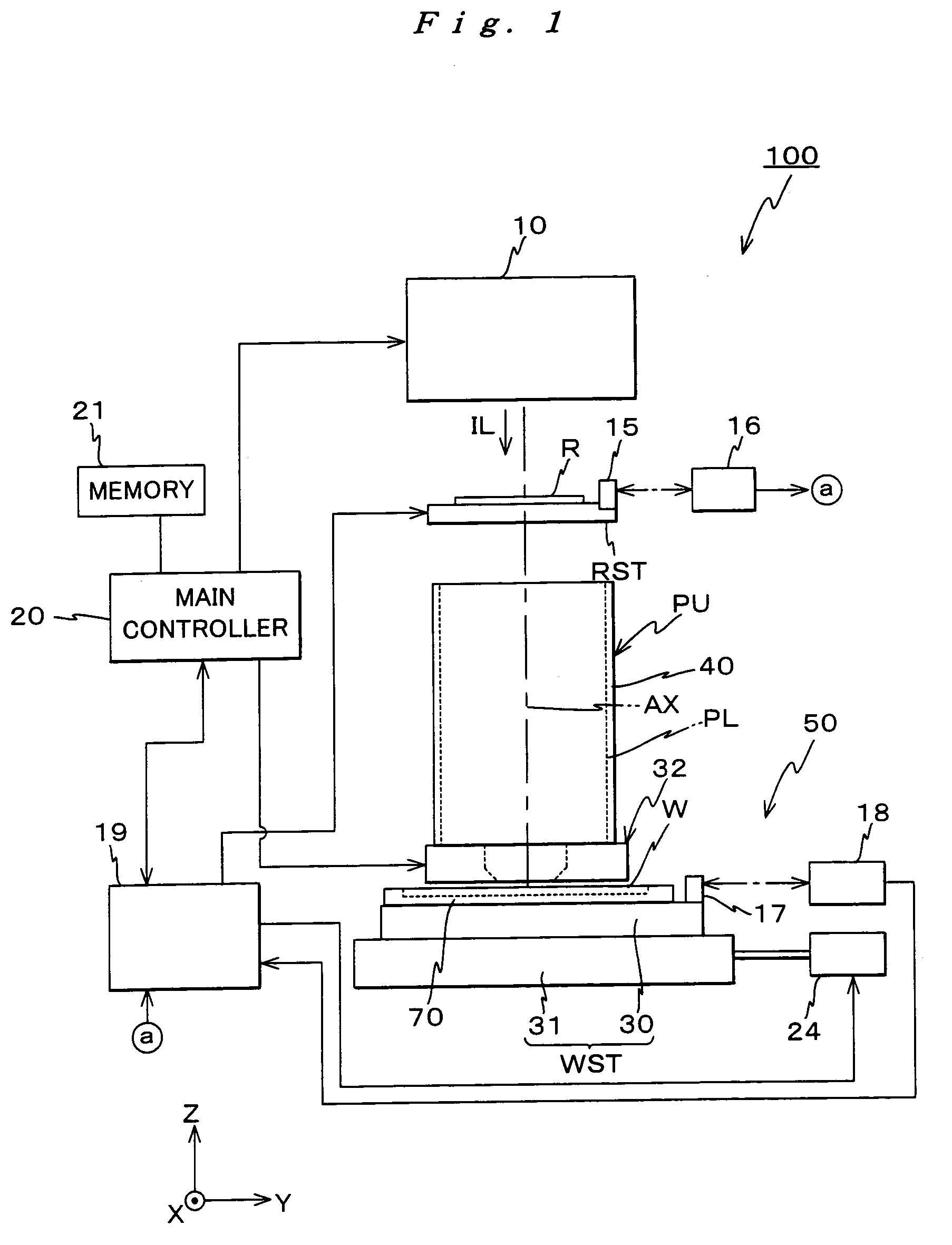
[0136]FIG. 1 is an entire view of an arrangement of an exposure apparatus 100 related to the first embodiment. Exposure apparatus 100 is a projection exposure apparatus, based on a step-and-scan method (the so-called scanning stepper). Exposure apparatus 100 comprises an illumination system 10, a reticle stage RST that holds a reticle R serving as a mask, a projection unit PU, a stage unit 50 that includes a Z tilt stage 30 on which a wafer W serving as a substrate is mounted, a control system for such parts, and the like.

[0137] As is disclosed in, for example, Japanese Patent Application Laid-open No. H06-349701 and its corresponding U.S. Pat. No. 5,534,970, the arrangement of illumination system 10 includes parts such as a light source, an illuminance uniformity optical system that includes an optical integrator or the like, a beam splitter, a relay lens, a variable ND filter, a re...

second embodiment

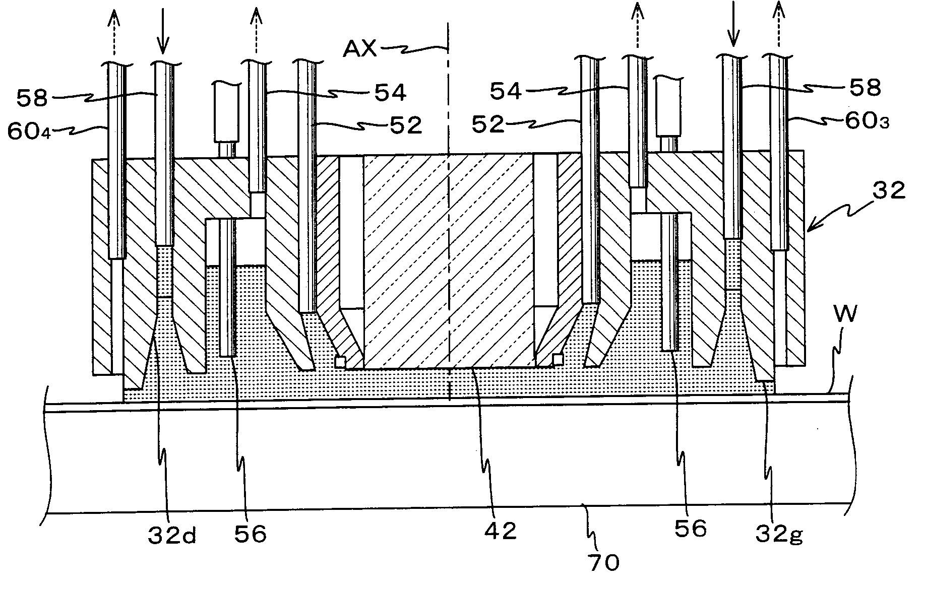
[0265] A second embodiment of the present invention is described below, referring to FIGS. 1A to 11F. For parts that have the same or similar arrangement as the first embodiment previously described, the same reference numerals will be used, and the description thereabout will be brief, or entirely omitted. The arrangement of an exposure apparatus in the second embodiment is similar to that of the first embodiment, other than the supply / drainage method of the water via liquid supply / drainage unit 32 by main controller 20. Accordingly, from the viewpoint of avoiding any repetition, the following description will be made focusing on the points different from the first embodiment.

[0266] In the exposure apparatus of the second embodiment, when operations other than the exposure operation based on the step-and-scan method is performed, more specifically, when wafer exchange and predetermined preparatory operations (reticle alignment, baseline measurement of the alignment detection syste...


PUM

PropertyMeasurementUnit
thicknessaaaaaaaaaa
wavelengthaaaaaaaaaa
refractive indexaaaaaaaaaa

Abstract

Liquid is supplied by a supply mechanism to a space between a lens and a wafer via a supply nozzle on one side of the lens, and the liquid is recovered by a recovery mechanism via a recovery pipe on the other side of the lens. When the supply and the recovery of the liquid are performed in parallel, a predetermined amount of liquid (exchanged at all times) is held between the lens and the substrate on the stage. Accordingly, when exposure (pattern transfer on the substrate) is performed in this state, an immersion method is applied and a pattern is transferred with good precision onto the substrate. In addition, in the case the liquid leaks out from under the lower edge of a peripheral wall, the liquid that could not be recovered is recovered by an auxiliary recovery mechanism via a slit. And, by such operations, the substrate is freed from the residual liquid on the substrate.

Description

CROSS-REFERENCE TO RELATED APPLICATIONS [0001] This is a continuation of International Application PCT / JP2003 / 015675, with an international filing date of Dec. 8, 2003, the entire content of which being hereby incorporated herein by reference, which was not published in English.BACKGROUND OF THE INVENTION [0002] 1. Field of the Invention [0003] The present invention relates to exposure apparatus and device manufacturing methods, and more particularly to an exposure apparatus that is used in a lithographic process when manufacturing electronic devices such as a semiconductor or a liquid crystal display device, and a device manufacturing method that uses such an exposure apparatus. [0004] 2. Description of the Related Art [0005] In a lithographic process to produce electronic devices such as a semiconductor (integrated circuit) or a liquid crystal display device, projection exposure apparatus are used that transfer an image of a pattern of a mask or a reticle (hereinafter generally re...

Claims


Application Information

Patent Timeline
Patent Type & Authority Applications(United States)
IPC IPC(8): G03F7/20
CPCG03F7/70341G03F7/709G03F7/70716G03F7/7015H01L21/027
Inventor HIRUKAWA, SHIGERUMAGOME, NOBUTAKATANAKA, ISSEY
Owner NIKON CORP
Why Eureka
Try Eureka