Methods for producing composite webs with reinforcing discrete polymeric regions

a technology of polymeric regions and composite webs, applied in the direction of liquid/solution decomposition chemical coating, instruments, photosensitive materials, etc., can solve the problems of reducing the stiffness of the entire surface of the web, and reducing the airflow of the web, so as to improve the formation of reinforcing discrete polymeric regions and improve the transfer of relatively large discrete polymeric regions

Inactive Publication Date: 2005-09-13
3M INNOVATIVE PROPERTIES CO
View PDF84 Cites 79 Cited by
  • Summary
  • Abstract
  • Description
  • Claims
  • Application Information

AI Technical Summary

Benefits of technology

[0007]Another advantage of the present invention may be found in the composite depressions and their use, which may improve the formation of reinforcing discrete polymeric regions in accordance with the present invention. The composite depressions may, e.g., improve the transfer of relatively large discrete polymeric regions onto the substrates as well as the transfer of discrete polymeric regions that have a varying thickness.
[0008]Another advantage of the methods of the present invention is the ability to provide one or more discrete polymeric regions that extend for the length of the substrate (while not being formed over the width of the substrate, i.e., the discrete polymeric regions are not coextensive with the major surface of the substrate).
[0009]Another advantage of the methods of the present invention is the ability to provide different thermoplastic compositions across the width of the substrate, such that some discrete polymeric regions may be formed of one thermoplastic composition, while other discrete polymeric regions are formed of a different thermoplastic composition.
[0010]Yet another advantage of the methods of the present invention is the ability to provide one or more discrete polymeric regions on both major surfaces of a substrate. The discrete polymeric regions on the opposing major surfaces may be formed with the same or different features as desired.
[0011]In one aspect, the present invention provides a method for producing a composite web, the method including providing a transfer roll having an exterior surface that includes one or more depressions formed therein, wherein the one or more depressions include at least one depression that includes a composite depression formed by a plurality of cells; and delivering a molten nonelastomeric thermoplastic composition onto the exterior surface of the transfer roll. The method further includes wiping the molten nonelastomeric thermoplastic composition from the exterior surface of the transfer roll, wherein a portion of the molten nonelastomeric thermoplastic composition enters the one or more depressions, and further wherein the portion of the molten nonelastomeric thermoplastic composition in the one or more depressions remains in the one or more depressions after wiping the molten nonelastomeric thermoplastic composition from the exterior surface of the transfer roll; and transferring at least a portion of the molten nonelastomeric thermoplastic composition in the one or more depressions to a first major surface of a substrate by contacting the first major surface of the substrate to the exterior surface of the transfer roll and the molten nonelastomeric thermoplastic composition in the one or more depressions, followed by separating the substrate from the transfer roll, wherein one or more discrete polymeric regions formed of the nonelastomeric thermoplastic composition are located on the first major surface of the substrate after separating the substrate from the transfer roll.
[0012]In another aspect, the present invention provides a method for producing a composite web, the method including providing a transfer roll with an exterior surface that includes one or more depressions formed therein, wherein the one or more depressions include at least one depression that includes a composite depression formed by a plurality of overlapping cells; and delivering a molten nonelastomeric thermoplastic composition onto the exterior surface of the transfer roll. The method also includes wiping the molten nonelastomeric thermoplastic composition from the exterior surface of the transfer roll, wherein a portion of the molten nonelastomeric thermoplastic composition enters the one or more depressions, and further wherein the portion of the molten nonelastomeric thermoplastic composition in the one or more depressions remains in the one or more depressions after wiping the molten nonelastomeric thermoplastic composition from the exterior surface of the transfer roll; and forcing a portion of a first major surface of a substrate into the one or more depressions, wherein the first major surface includes a porous surface including fibers, and wherein a portion of the nonelastomeric thermoplastic composition in the one or more depressions infiltrates the porous surface, and still further wherein the molten nonelastomeric thermoplastic composition encapsulates at least a portion of at least some of the fibers. The method further includes separating the substrate from the transfer roll, wherein one or more discrete polymeric regions formed of the nonelastomeric thermoplastic composition are located on the first major surface of the substrate after separating the substrate from the transfer roll.

Problems solved by technology

Such approaches can, however, add cost and weight to the web, as well as stiffness over the entire surface of the web—even in those areas that do not require reinforcement.
Furthermore, reinforcing layers that are coextensive with the web may also reduce its breathability.
The handling and attachment of such discrete pieces can, however, be problematic, by potentially reducing throughput, causing waste (where the discrete pieces are not securely attached), requiring precise registration or location on the web, requiring the use of adhesives or other bonding agents, etc.
The discrete pieces may also present relatively sharp that may be the source of irritation or discomfort.
The irritation or discomfort can be exacerbated because the reinforcing pieces are typically located on the surface of the substrate.

Method used


Image

  • Methods for producing composite webs with reinforcing discrete polymeric regions
  • Methods for producing composite webs with reinforcing discrete polymeric regions
  • Methods for producing composite webs with reinforcing discrete polymeric regions

Examples


example 1

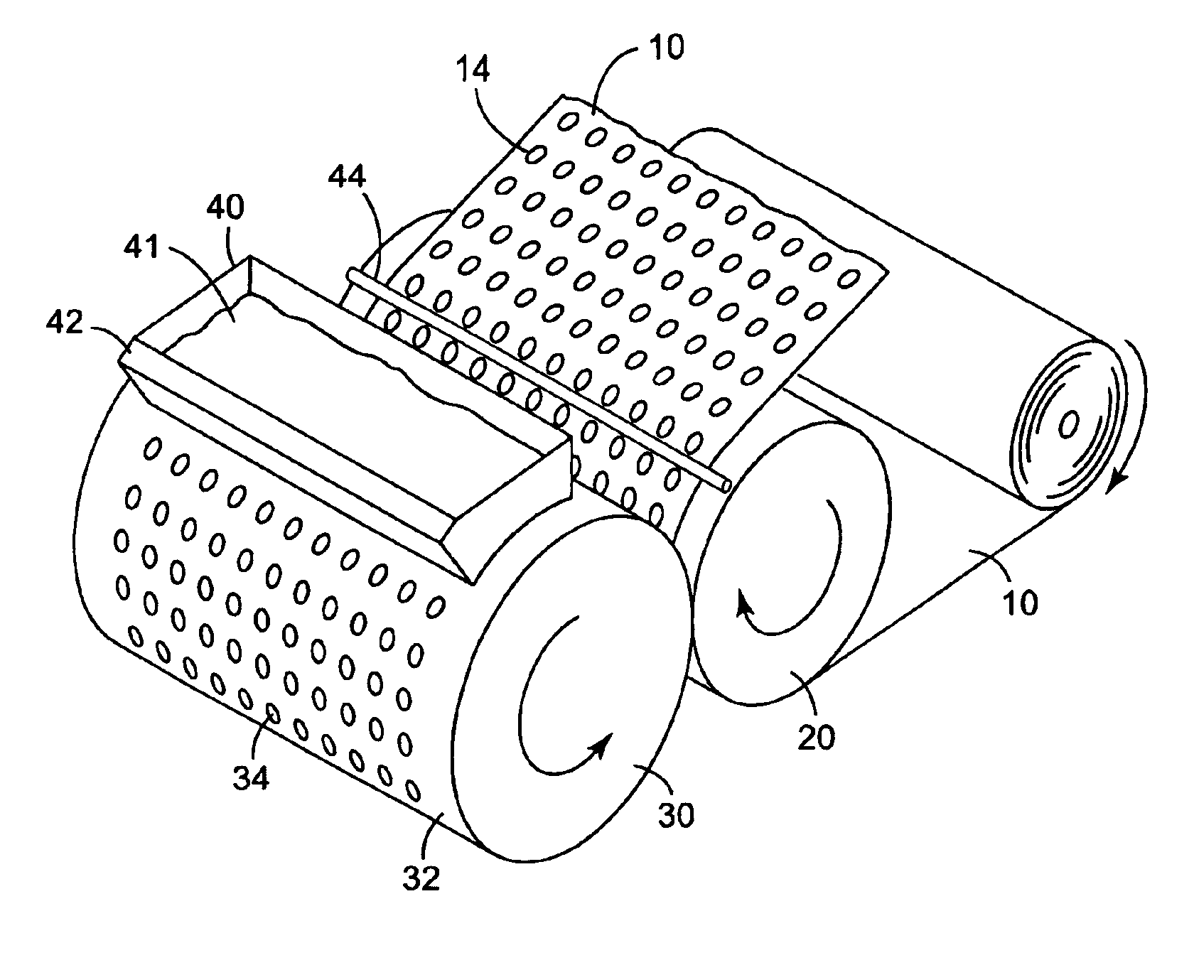
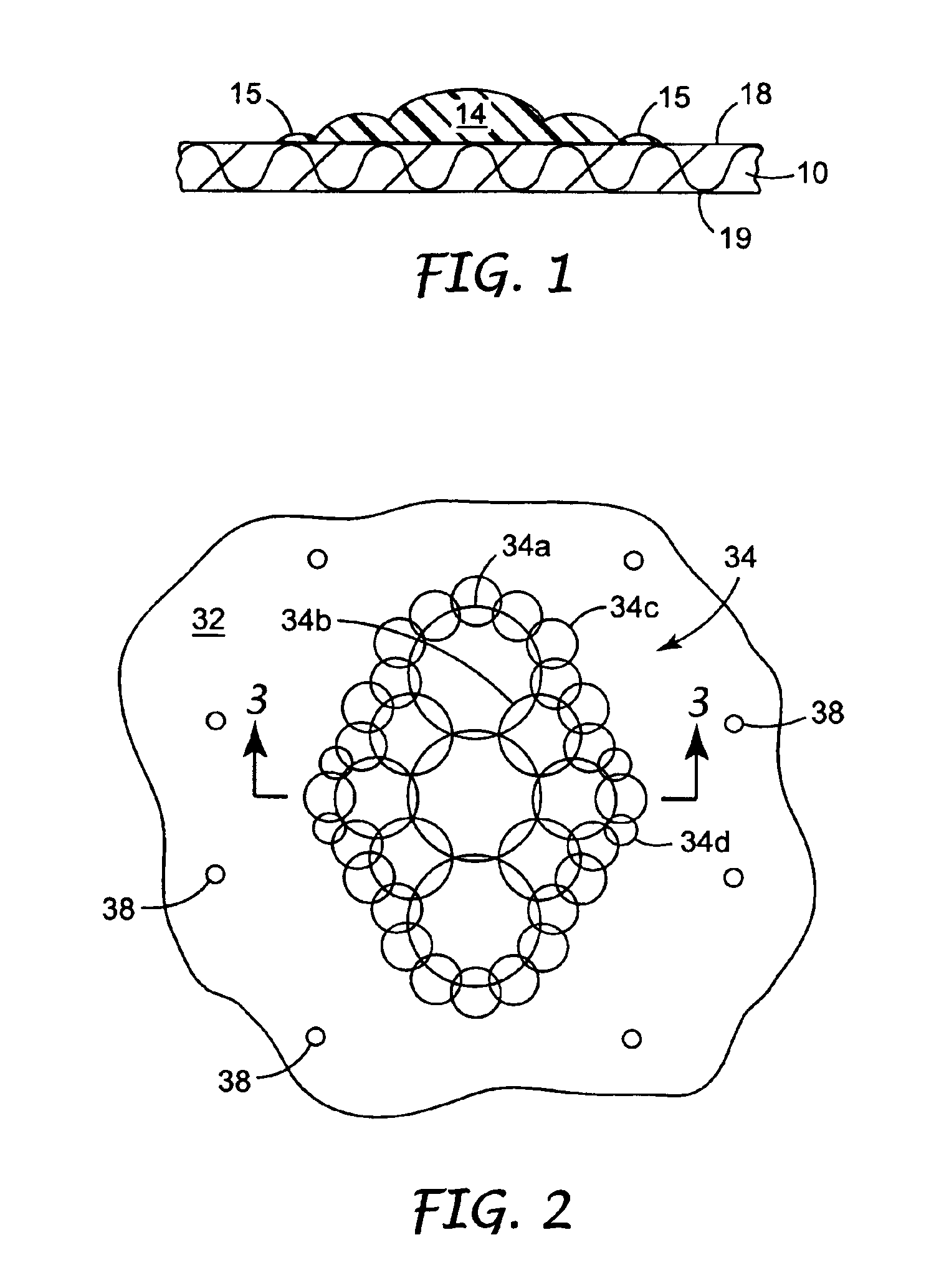
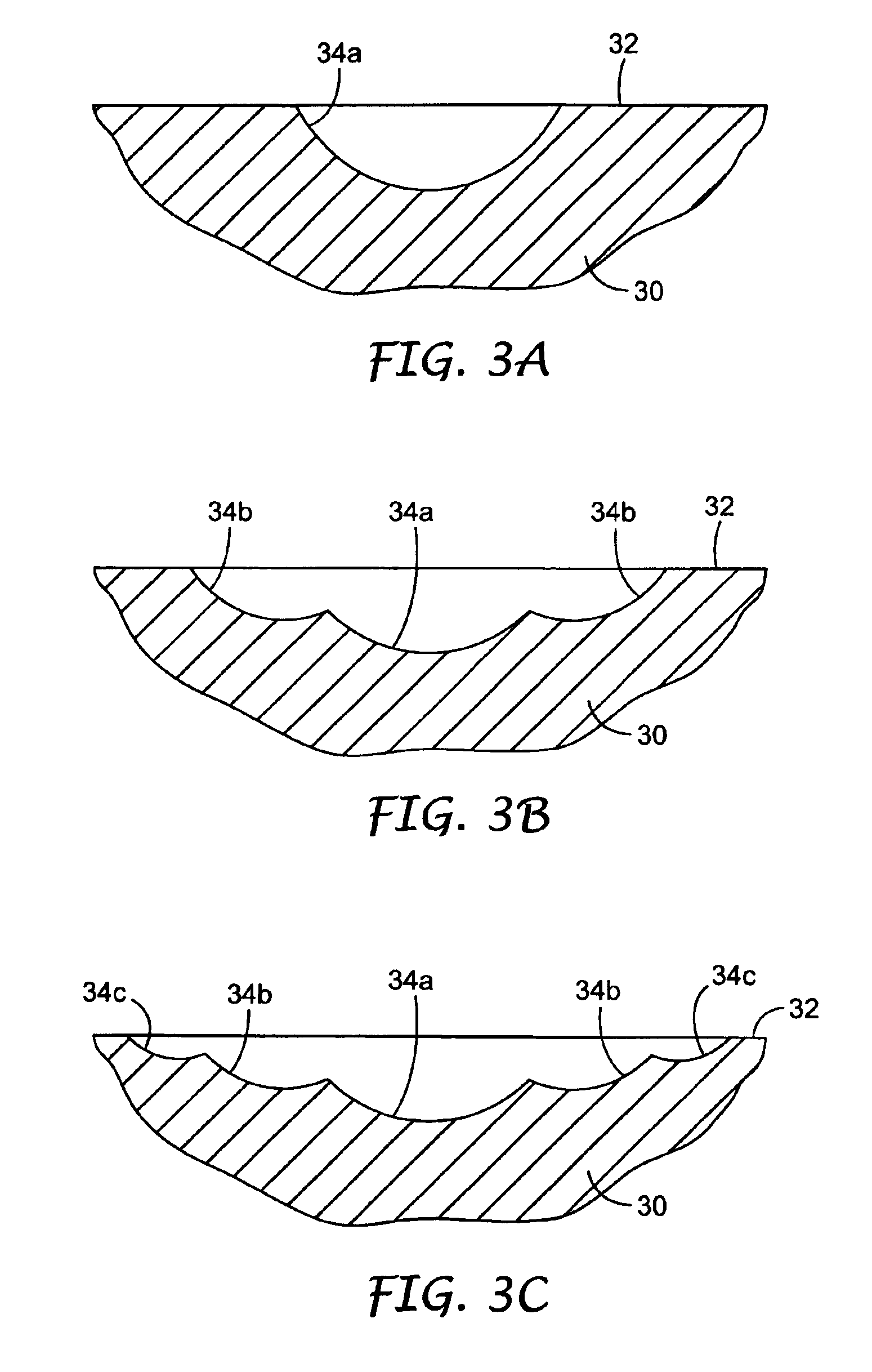
[0129]A web of the present invention was produced using a system similar to that shown in FIG. 11. A 40 mm diameter twin screw extruder fitted with a gear pump was used to deliver a molten polypropylene polymer (SC-917, Basell Olefins) at a melt temperature of approximately 227° C. to a neck tube. The neck tube was positioned such that a thick strand of molten polymer was extruded vertically downward onto the exterior surface 32 of an oil-heated steel transfer roll 30 having a diameter of 23 cm. The exterior surface of the transfer roll was machined using a computer controlled milling machine to have a circle of 8 depressions around the periphery of the roll near the center of the roll. The depressions were elliptical in shape 7.6 cm long and 1.9 cm in width at the widest point of the ellipse. The long axis of each ellipse was parallel to the machine direction (downweb). The ellipses were arranged with a center-to-center spacing of 8.9 cm. The elliptical depressions were machined in...

example 2

[0133]To demonstrate that two or more discrete reinforcing polymer regions can be transferred to two substrates followed by lamination of the substrates, a web was prepared as in Example 1 using the apparatus shown in FIG. 11 except a second transfer roll, identical to the transfer roll 30, a second rubber backup roll, similar to the rubber backup roll 20, a second doctor blade, similar to the doctor blade 42, and a second hot wire, similar to the hot wire 44, were used to transfer a discrete reinforcing polymer region to a second nonwoven substrate (SONTARA 8001 spunlaced polyester, Dupont). Molten polypropylene polymer (SC-917, Basell Olefins) was delivered to the second transfer roll at a melt temperature of approximately 227° C. The second transfer roll was at approximately 227° C., and the second rubber backup roll was at approximately 23° C. A nip pressure of 25 N / lineal cm was used. The doctor blade pressure against the second transfer roll was approximately 123 N / lineal cm. ...


PUM

PropertyMeasurementUnit
volumeaaaaaaaaaa
areaaaaaaaaaaa
lengthsaaaaaaaaaa

Abstract

Methods of manufacturing composite webs including a substrate with one or more reinforcing discrete polymeric regions located on or within the composite web are disclosed. Molten nonelastomeric thermoplastic material of the discrete polymeric region is forced against the substrate by a transfer roll. If the substrate is porous, fibrous, etc., a portion of the nonelastomeric thermoplastic composition may infiltrate the substrate and/or encapsulate fibers of the substrate.

Description

FIELD OF THE INVENTION[0001]The present invention relates to methods of manufacturing composite webs that include reinforcing discrete polymeric regions.BACKGROUND[0002]The manufacture of articles formed of webs that require some reinforcement to withstand forces experienced during use are known. In many cases, reinforcement is simply provided over the entire substrate or web. Such approaches can, however, add cost and weight to the web, as well as stiffness over the entire surface of the web—even in those areas that do not require reinforcement. Furthermore, reinforcing layers that are coextensive with the web may also reduce its breathability.[0003]To address some of these issues, smaller pieces of reinforcing materials may be attached to a web or substrate in selected areas that require reinforcement. The handling and attachment of such discrete pieces can, however, be problematic, by potentially reducing throughput, causing waste (where the discrete pieces are not securely attac...

Claims


Application Information

Patent Timeline
Patent Type & Authority Patents(United States)
IPC IPC(8): B29C43/46B29C43/28B29C43/22B29C43/44B05D1/28B05D7/24D04H1/54D04H1/70D06M15/227
CPCB29C43/222B29C43/28B29C43/46
Inventor ALBERG, RANDALL L.EATON, BRADLEY W.WOOD, LEIGH E.
Owner 3M INNOVATIVE PROPERTIES CO
Why Eureka
Try Eureka