Determination of a channel estimate of a transmission channel

a technology of transmission channel and channel estimate, which is applied in the direction of transmission monitoring, pulse technique, dc level restoring means or bias distort correction, etc., can solve the problems of high interference, large and highly localized amplitude and phase shift of signals, and thermal noise, so as to improve the channel estimate for one channel, improve the channel estimate, and improve the estimate. the effect of accuracy

Active Publication Date: 2009-07-14
TELEFON AB LM ERICSSON (PUBL)
View PDF8 Cites 760 Cited by
  • Summary
  • Abstract
  • Description
  • Claims
  • Application Information

AI Technical Summary

Benefits of technology

[0018]Hence by using the estimates of two channels, and determining a scale factor relating the channel estimates of the two channels, the channel estimate for one of the channels is improved. Hence, the method utilises the fact that the difference between the channels can substantially be described by a scale factor, also called a gain offset. Consequently, by determining an estimate of the scale factor, an improved estimate of the channel estimate is provided.
[0019]By applying a Least Squares Error criterion to estimate the scale factor a high accuracy of the estimate is achieved. It is a further advantage of the method that it only requires a low computational complexity and may be implemented in cost and power efficient way, e.g. as a digital signal processing (DSP) implementation.
[0020]In particular, a low-complex method of determining a channel estimate may advantageously be used in the context of SIR estimation, since SIR estimation typically should be done very fast in order to fulfil power control timing requirements.
[0022]Furthermore, it is noted that the above method based on a least squares approach may be implemented by means of linear operations, thereby considerably reducing the required complexity.
[0027]Furthermore, it is noted that in many communications systems, the information carried by a channel is organized in a plurality of time slots that are grouped in a succession of frames. Each slot may comprise a payload and additional information including pilot symbols, transmit power control (TPC) commands, etc. In one exemplary communications system, slots may have durations of 0.625 milliseconds and include variable numbers of bits, depending on the types of slots. The gain offset between two adjacent slots depends on the TPC command transmitted by the receiver during a previous slot. Hence, that knowledge can be incorporated to improve the gain offset estimation and, therefore, also the SIR estimation performance. Accordingly, in another preferred embodiment, the objective function further comprises a second term dependant on a gain offset determined for a previous time slot and on a TPC command transmitted during a previous time slot.
[0029]Furthermore it is recognised that the performance gain achieved by the invention may depend on the current radio access bearer (RAB). For example, the performance gain is larger for RABs with low average DPCH power (implying a large spreading factor) and with few DPCH pilots. Hence, in a preferred embodiment, the above steps are performed conditioned on information received from a higher layer, e.g. the current RAB, thereby adapting the estimation method to the current RAB in order to reduce the complexity and, therefore, the power consumption.

Problems solved by technology

In a medium, such effects on a radio-frequency signal primarily include multipath fading, interference from other signals passing through the medium, and thermal noise.
Fading is caused by the interaction of the signal with reflections or echoes of itself, and may result in large and highly localized amplitude and phase shifts of the signal.
In a radio environment, interference is often caused by the unwanted presence of other radio signals.
Thermal noise is present in all communication channels, and causes additional distortion of the transmitted signal.
Since the DPCH is power controlled and there are only relatively few pilot symbols on the DPCH, the obtained channel estimates and, therefore, also the obtained SIR estimates are noisy.
Such prior art systems typically suffer from noisy channel estimates causing a reduced system performance in terms of precision and accuracy of the channel estimates and, thus, the subsequent SIR estimation.
A low precision and accuracy of the SIR estimate, in turn, significantly affect the power control performance of a communications system and, consequently, the capacity of the communications system.

Method used


Image

  • Determination of a channel estimate of a transmission channel
  • Determination of a channel estimate of a transmission channel
  • Determination of a channel estimate of a transmission channel

Examples


first embodiment

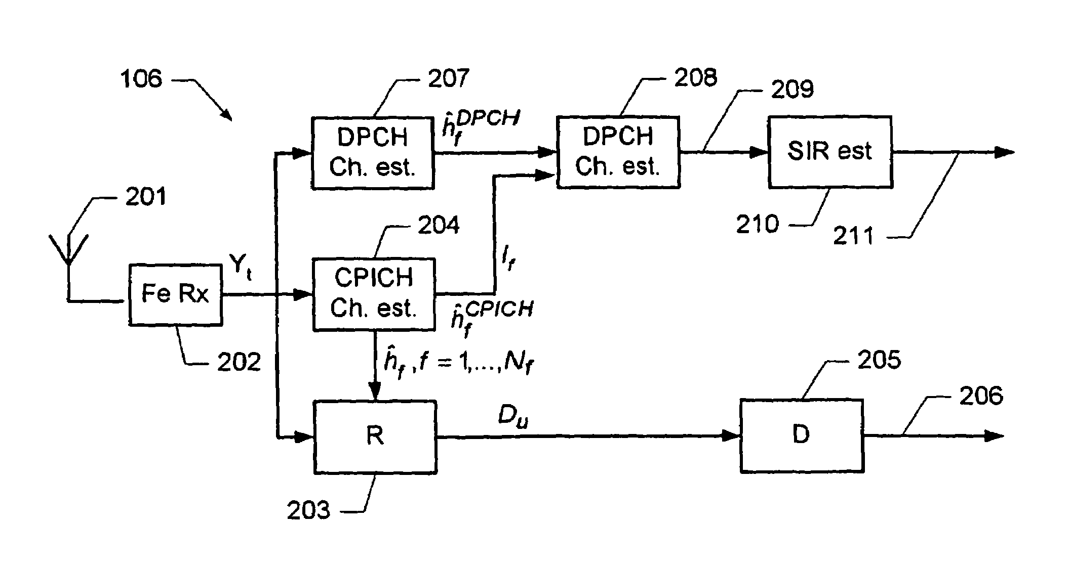
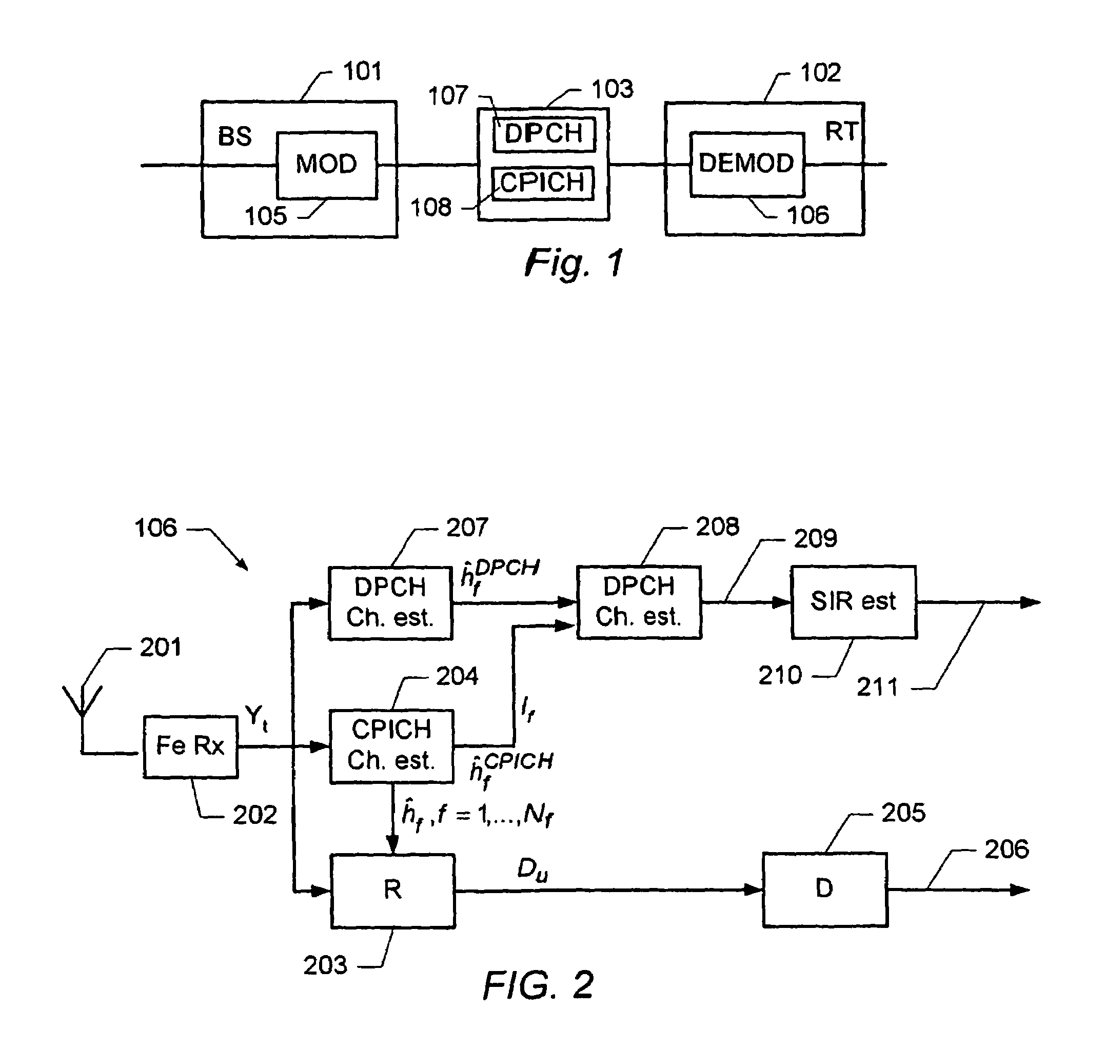
[0066]FIG. 2 schematically shows a block diagram of a receiver including an arrangement for estimating a SIR. The receiver, generally designated 106, comprises a front-end receiver 202 that down-converts and samples the received radio signal to a digital baseband signal Yt. The receiver 106 further comprises a dedicated channel estimation unit 207, a common pilot estimation unit 204, and a RAKE receiver 203, each of which receive the digital baseband signal Yt. The RAKE receiver uses several baseband correlators in the so-called fingers of the RAKE receiver in order to individually process several signal multipath components according to a corresponding propagation delay and channel estimate. The correlator outputs are combined to achieve improved communications reliability and performance (see e.g. “Digital Communications” 4th Edition, by John G. Proakis, McGraw-Hill, 2000). The RAKE receiver generates signal symbols Du which are fed to a decoder 205.

[0067]The channel estimation un...

second embodiment

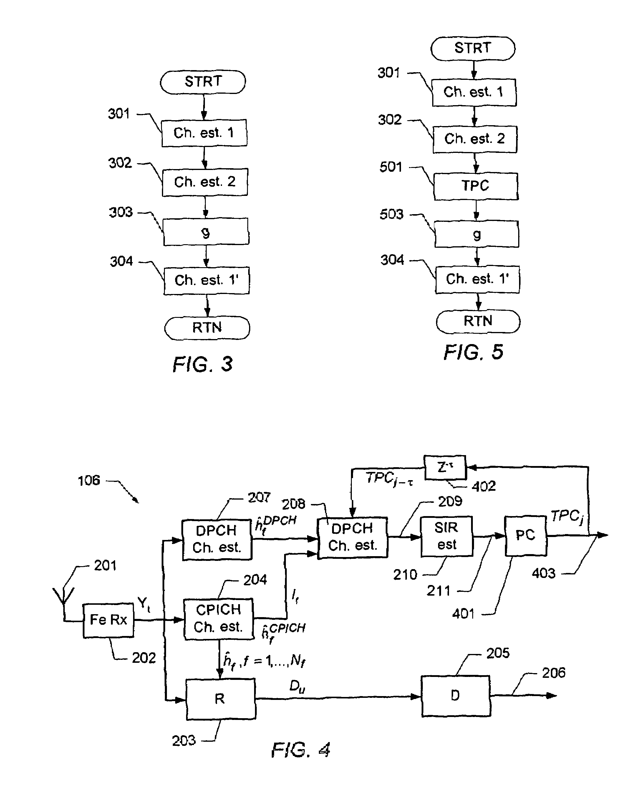
[0083]FIG. 4 schematically shows a block diagram of a receiver including an arrangement for estimating a SIR. According to this embodiment, the channel estimate is further based on power control commands of a power control loop. The receiver according to this embodiment is similar to the receiver described in connection with FIG. 2. The receiver further comprises a power control unit 401. The power control unit implements a closed loop power control of the power at which the receiver receives the communications signals on the DPCH. In particular, the transmitted power on the DPCH in slot j is changed by a factor 10ΔTPCTPCj−1 relative to a previous slot j−1. Here, ΔTPC is a fixed power increment set by the network, i.e. ΔTPC determines by which amount the power is incremented. In some communications networks, the value of ΔTPC is signaled to the receiver. However, in other systems this may not be the case. Furthermore, TPCj−τ represents a power control command determined by the recei...

third embodiment

[0099]FIG. 6 schematically shows a block diagram of a receiver including an arrangement for estimating a SIR. The receiver according to this embodiment is similar to the receiver described in connection with FIG. 2. According to this embodiment, the receiver further comprises a control unit 601 that receives information 602 from a higher layer (not explicitly shown) of the communications model implemented by the receiver. In one embodiment, the control unit receives information about the current radio access bearer (RAB), e.g. information about the slot formats, information about the number of pilot symbols in the dedicated channel, information about spreading factors, etc. Based on this information the control unit generates a control signal 603 which is fed into the channel estimation block 208 to control the channel estimation and / or the subsequent SIR estimation process.

[0100]For instance, if a low rate data channel with high spreading factor and few DPCH pilot symbols are used,...


PUM


Abstract

A method of determining a channel estimate of a first transmission channel in a communications system. The method comprises deriving a first set of channel estimates from symbols received through said first transmission channel; deriving a second set of channel estimates from symbols received through a second transmission channel in the communications system; determining a scale factor between the first and second sets of channel estimates from a least squares error criterion; and determining the channel estimate of the first transmission channel as a channel estimate of the second transmission channel scaled by the determined scale factor.

Description

CROSS REFERENCE TO RELATED APPLICATIONS[0001]This application claims the benefit of U.S. Provisional Application No. 60 / 472,483 filed May 21, 2003, which is hereby incorporated herein by reference in its entirety. This application additionally claims foreign priority benefits under 35 U.S.C. §§119(a)-(d) or (f), or 365(b) of PA 2003 00748 filed in Denmark on May 19, 2003 and of 03388067.5 filed in Europe on Oct. 13, 2003, both of which are hereby incorporated herein by reference in their entireties.FIELD OF THE INVENTION[0002]This invention relates to the determination of a channel estimate of a transmission channel. The invention further relates to the determination of a signal-to-interference ratio based on a channel estimate.BACKGROUND OF THE INVENTION[0003]In a digital communications system, digital symbols representing information are transmitted between different nodes (e.g., base stations, mobile phones) to exchange information.[0004]A layered model often referred to as the O...

Claims


Application Information

Patent Timeline
Patent Type & Authority Patents(United States)
IPC IPC(8): H03K9/00H04B1/707H04L5/02H04L25/02H04L25/06
CPCH04L5/023H04L25/0226H04W52/362H04L25/067H04L25/0228H04W52/16H04B1/7085H04B1/7115
Inventor JONSSON, ELIASNILSSON, JOHANLINDOFF, BENGT
Owner TELEFON AB LM ERICSSON (PUBL)
Why Eureka
Try Eureka