Video processing

Inactive Publication Date: 2005-01-27
BRITISH BROADCASTING CORP
View PDF8 Cites 141 Cited by
  • Summary
  • Abstract
  • Description
  • Claims
  • Application Information

AI Technical Summary

Benefits of technology

[0022] Optionally selected objects in the desired view are rendered as projections of real images of those objects obtained from said real scene image, optionally by transforming real image data based on the relationship of the real viewpoint of the camera from which the image is taken and the selected desired viewpoint. In a simple embodiment, real images of the selected objects are obtained and used as flat models oriented perpendicular to the optical axis of the real camera. These models can then be rendered from the point of view of the selected viewpoint by projection. This simple approach has been found to produce surprisingly good results, particularly when the selected viewpoint and the real camera viewpoint differ in angle by less than approximately 30 degrees.
[0023] In some cases, beneficial results may be achieved by obtaining images of selected objects, and allowing the images to be rotated when modelling the objects. The objects can be rendered from a selected viewpoint by rotating the images, either partially up to a defined limit or up to an amount which is a function of the angle between the real and

Problems solved by technology

The use of virtual reality techniques is becoming increasingly common in television and video production, however application in sports coverage is at present relatively limited.
This system is limited however to relatively simple graphics, and works with a camera at a fixed position.
However the large number of cameras required to achieve a sufficiently precise view makes this solution too costly or impractical for many events.
A number of systems exist for cameras on rails and wires (e.g. [www.aerialcamerasystems.com], however it cannot be guaranteed that the camera will be in the right place in the right time to produce the desired image, and the producer cannot change his/her mind after the event.
This is an expensive solution, and quite slow in use.
A particular disad

Method used


Image

  • Video processing
  • Video processing
  • Video processing

Examples


Embodiment Construction

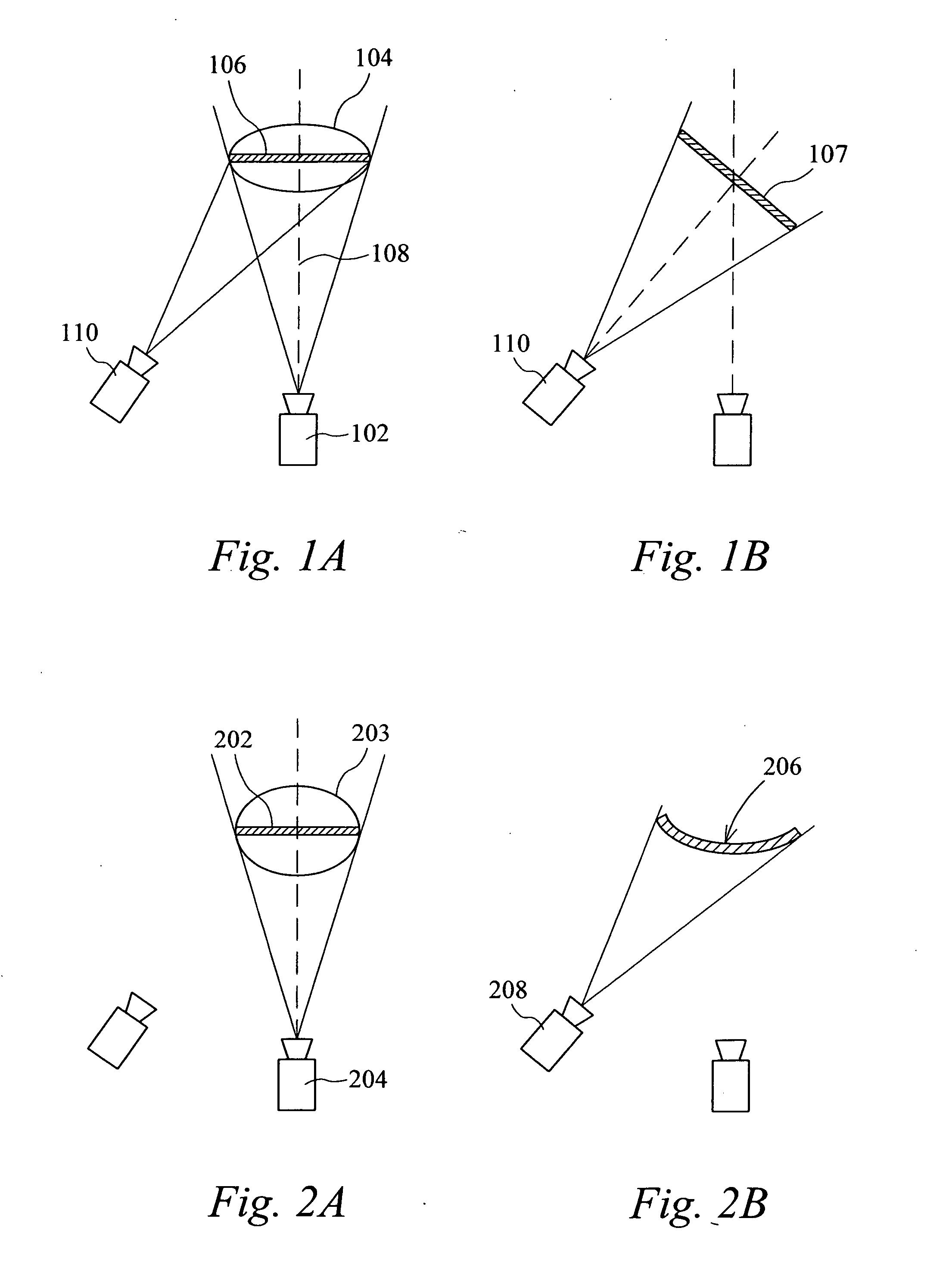
[0087] It can be seen in FIG. 1a that using a single real camera 102 we can model a selected object 104 most simply as a 2-D plane 106 at right angles to the real camera axis 108. The images from the real camera are rendered as a flat texture from the position of the virtual camera 110. An observer at the virtual view point sees the virtual object as a “cardboard cut-out”. This approach works reasonably well when the difference between the real and virtual camera angles is up to about 30 degrees, beyond which the distortion becomes too apparent.

[0088] A variation of the 2-D approach is illustrated in FIG. 1b, in which the planes modelling selected objects are rotated to a suitable angle 107. In some situations this may give a better virtual view, for example where the angle of view of the main camera is relatively narrow (otherwise the 2-D image will not have enough horizontal resolution), and the 2-D image is approximately perpendicular to the virtual camera 110.

[0089] A “2½-D” a...


PUM


Abstract

A method for generating a desired view of a real scene from a selected desired viewpoint by identifying objects in a real image, determining the positions of the identified objects, and rendering a view of the scene from a selected viewpoint using image data from the real image to render at least some of the identified objects. Other portions of the rendered view can be rendered using other source data which may be generic or historic. Identified objects may be tracked over a period of time to determine a trajectory or path. A user interface can be provided to assist in object tracking. A number of cameras can be used to provide a number of real images, and certain cameras may be controlled using the parameters of other cameras.

Description

PRIORITY INFORMATION [0001] This application claims benefit and priority to United Kingdom Application No. 0305926.8 Filed 14 Mar. 2003 entitled “Video Processing”, the contents of which is incorporated herein by reference. BACKGROUND OF THE INVENTION [0002] This invention relates to video processing, and more specifically to virtual image production. The present invention may be used in a number of different areas of video and image production, but is particularly applicable in the field of television sports coverage. [0003] The use of virtual reality techniques is becoming increasingly common in television and video production, however application in sports coverage is at present relatively limited. Replays, slow motion and detailed analysis of sports events are popular, and there is a growing desire to be able to provide computer enhanced images and sequences for these purposes. A wide variety of virtual techniques have been proposed in the field of video and television productio...

Claims


Application Information

Patent Timeline
IPC IPC(8): G06T15/20G06V10/147H04N5/222H04N15/00
CPCG06K9/209H04N5/222G06T15/20G06V10/147G06T7/70
Inventor THOMAS, GRAHAM ALEXANDERBRIGHTWELL, PETERGRAU, OLIVER
Owner BRITISH BROADCASTING CORP
Why Eureka
Try Eureka