Focused ultrasound ablation devices having selectively actuatable emitting elements and methods of using the same
Inactive Publication Date: 2009-11-10
MEDTRONIC INC
View PDF501 Cites 243 Cited by
Summary
Abstract
Description
Claims
Application Information
AI Technical Summary
This helps you quickly interpret patents by identifying the three key elements:
Problems solved by technology
Method used
Benefits of technology
[0022]Some of the advantages of the present invention are that the outcome of ultrasound ablation procedures in various areas of the body is greatly enhanced, a single focused ultrasound ablation device can optimally be used in various ablation procedures in various areas of the body, anatomical tissue around, between or surrounding the lesion segments can be left lesion free, a focused ultrasound emitting member having a particular array of transducer elements can be used to form lesions corresponding in size and/or configuration to the size and/or configuration of the array as well as lesions having sizes and/or configurations different from the size and/or configuration of the array, the focused ultrasound emitting member can be coupled with a handle for hand-held use and operation thereof, the focused ultrasound ablation device does not have to be customized for use in a specific area of the body, and the focused ultrasound emitting member can be provided in a focused ultrasound ablation device provided as a standardized instrument capable of being used in or on a wide variety of areas of patients' bodies.
[0023]These and other objects, advantages and benefits are realized with the present invention as generally characterized in a focused ultrasound ablation device including an ultrasound emitting member having a plurality of individual ultrasound emitting elements arranged thereon in an array. The ultr
Problems solved by technology
Thermal effects include heating of the anatomical tissue; and, when the tissue is heated to a sufficiently high temperature, tissue damage such as coagulative necrosis is produced.
H
Method used
Image
Click on the blue label to locate the original text in one second.
Reading with bidirectional positioning of images and text.
Examples
Example
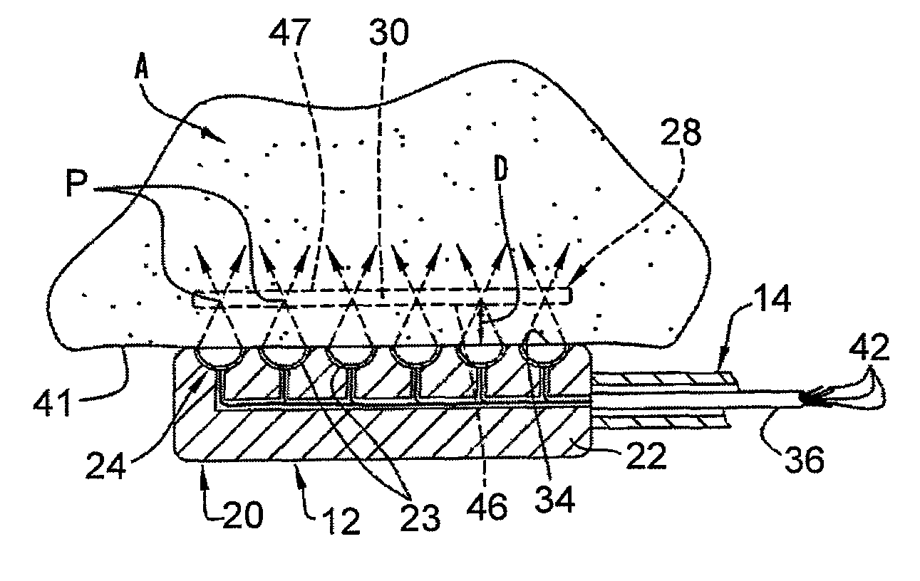
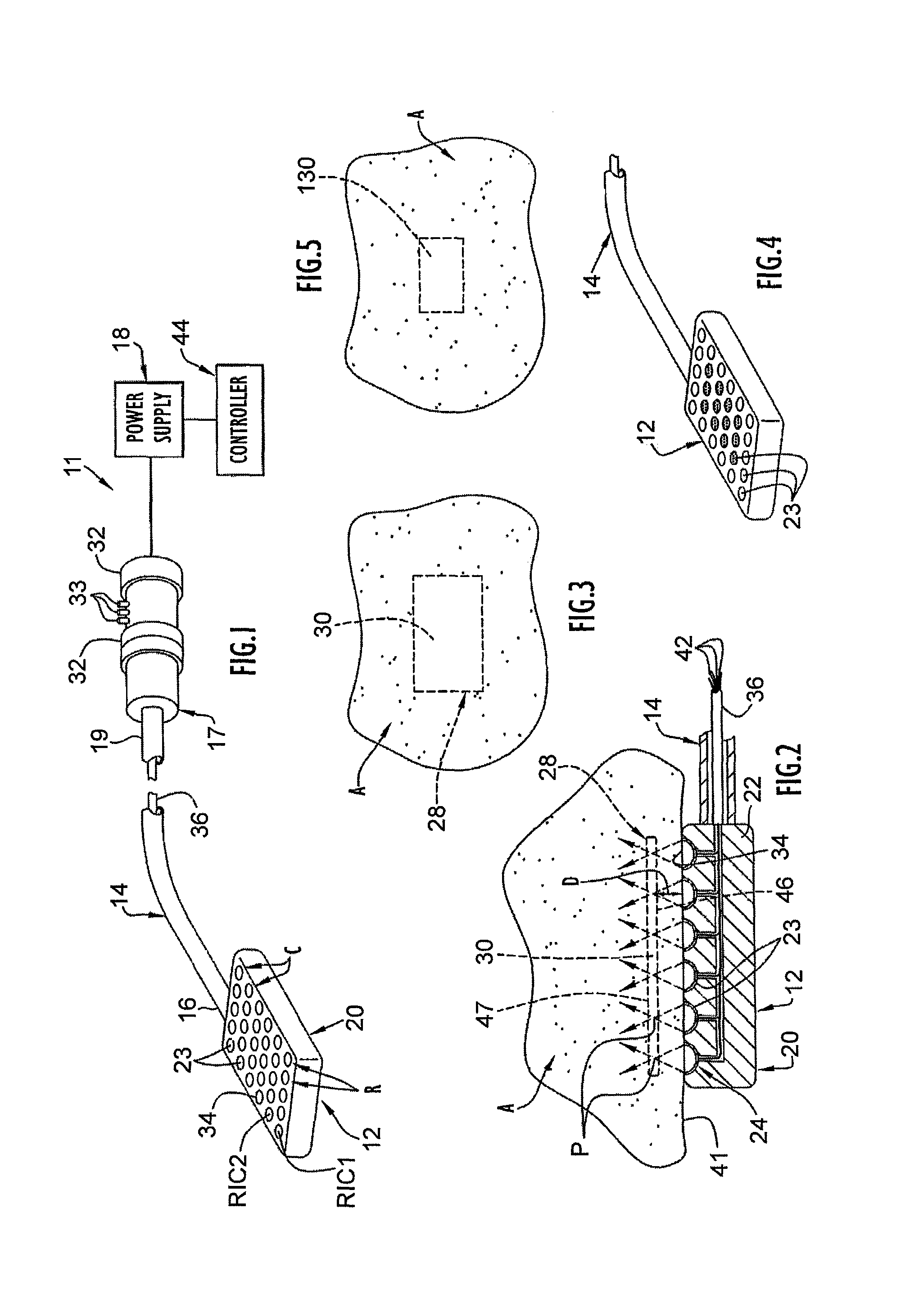
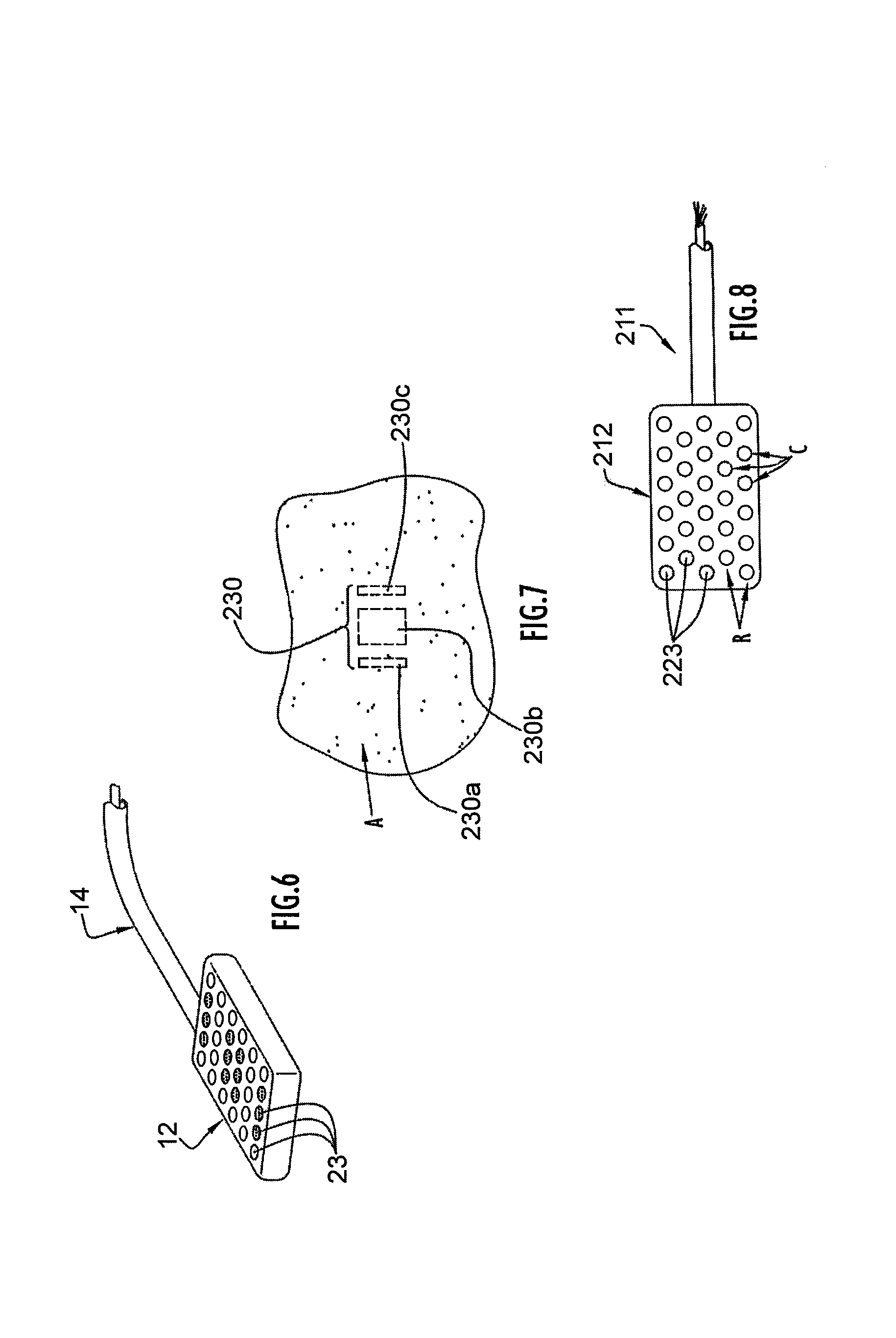
[0033]A high intensity focused ultrasound ablation device 11 incorporating a focused ultrasound emitting member 12 according to the present invention is illustrated in FIG. 1. The focused ultrasound ablation device 11 includes ultrasound emitting member or element 12, an elongate handle shaft or handle body 14 having a distal end 16 at which the ultrasound emitting member 12 is disposed and a handle or handpiece 17 coupled to a proximal end 19 of handle shaft 14. As shown in FIG. 2, the ultrasound emitting member 12 includes a transducer 20 carried by a housing 22 and capable of generating and emitting ultrasound energy in response to being supplied with electrical power from a power supply 18. The transducer 20 includes a plurality of individual ultrasound emitting elements, transducers or transducer elements 23, each including a piezoelectric element 24 that vibrates to produce ultrasound energy when electrical current is supplied thereto. The transducer elements 23 have a focusin...
PUM
Abstract
A focused ultrasound ablation device and method includes an ultrasound emitting member having a plurality of individual ultrasound emitting elements arranged in an array. The ultrasound emitting elements are actuatable to emit ultrasound energy and focus the emitted ultrasound energy a predetermined distance from the ultrasound emitting member such that the ultrasound energy is focused within anatomical tissue adjacent which the ultrasound emitting member is positioned. The anatomical tissue is heated by the ultrasound energy focused therein to form an internal lesion within the tissue. The ultrasound emitting elements are selectively, independently actuatable, allowing selected ones of the ultrasound emitting elements to be actuated to emit ultrasound energy to obtain a lesion of desired or selected size and/or surface configuration in the tissue of a particular patient.
Description
CROSS-REFERENCE TO RELATED PATENT APPLICATIONS[0001]This application is a continuation of U.S. patent application Ser. No. 09 / 487,710 filed Jan. 19, 2000 now U.S. Pat. No. 6,692,450, the disclosure of which is incorporated herein by reference.[0002]This application is related to U.S. patent applications Ser. No. 09 / 487,708 filed Jan. 19, 2000, now abandoned and entitled Methods of Soft Palate Reduction By Thermal Ablation Using High Intensity Focused Ultrasound, Ser. No. 09 / 487,707 filed Jan. 19, 2000, now U.S. Pat. No. 6,413,254 and entitled Methods of Tongue Base Reduction By Thermal Ablation Using High Intensity Focused Ultrasound, Ser. No. 09 / 487,709 filed Jan. 19, 2000, now abandoned and entitled Methods of Tonsil Reduction By Thermal Ablation Using High Intensity Focused Ultrasound, Ser. No. 09 / 487,706 filed Jan. 19, 2000, now abandoned and entitled Methods of Turbinate Or Other Soft Tissue Reduction By Thermal Ablation Using High Intensity Focused Ultrasound, Ser. No. 09 / 487,...
Claims
Application Information
Patent Timeline
Application Date:The date an application was filed.
Publication Date:The date a patent or application was officially published.
First Publication Date:The earliest publication date of a patent with the same application number.
Issue Date:Publication date of the patent grant document.
PCT Entry Date:The Entry date of PCT National Phase.
Estimated Expiry Date:The statutory expiry date of a patent right according to the Patent Law, and it is the longest term of protection that the patent right can achieve without the termination of the patent right due to other reasons(Term extension factor has been taken into account ).
Invalid Date:Actual expiry date is based on effective date or publication date of legal transaction data of invalid patent.