
Physical resynthesis of a logic design

a logic design and physical synthesis technology, applied in the field of electronic design automation of logic design, can solve the problems of increasing complexity of programmable logic integrated circuits such as pals, plds, fpgas, and increasing difficulty in ensuring the implementation of logic functions in an optimal way, so as to improve the performance of a design, improve the efficiency of logic, and improve the effect of design performan

Inactive Publication Date: 2008-02-26
ALTERA CORP
View PDF10 Cites 140 Cited by
  • Summary
  • Abstract
  • Description
  • Claims
  • Application Information

AI Technical Summary

Benefits of technology

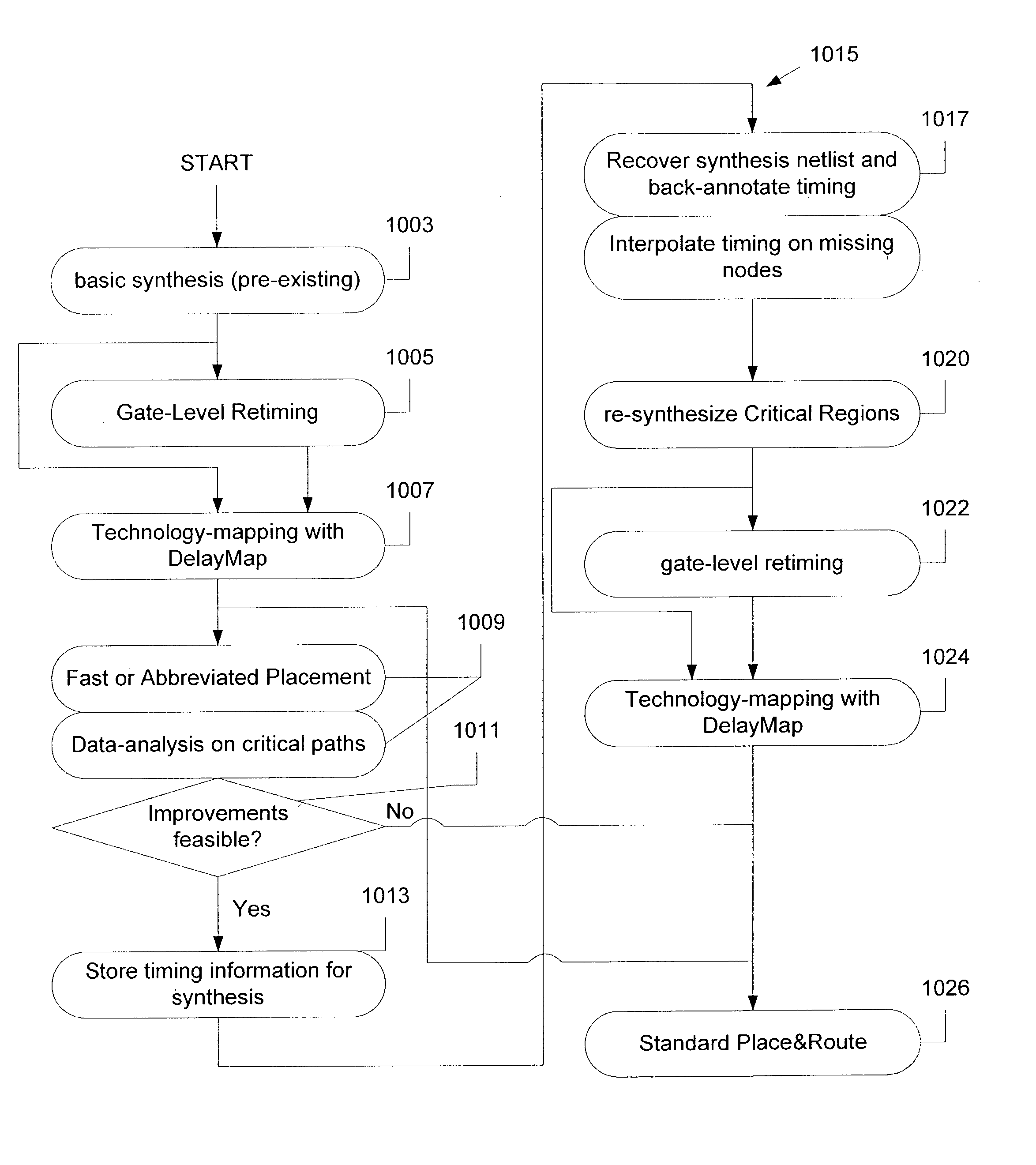
[0008]A multiple-pass synthesis technique improves the performance of a design. In a specific embodiment, synthesis is performed in two or more passes. In a first pass, a first synthesis is performed, and in a second or subsequent pass, a second synthesis or resynthesis is performed. During the first synthesis, the logic will be mapped to for example, the logic structures (e.g., logic elements, LUTs, synthesis gates) of the target technology such as a programmable logic device. Alternatively a netlist may be provided from a third party. Before the second synthesis, a fast or abbreviated fit may be performed of the netlist to a specific device (e.g., specific programmable logic device product). Before the second synthesis, the netlist obtained from the first synthesis (or provided by a third party) is unmapped and then the second synthesis is performed. Since a partial fit is performed, the second synthesis has more visibility and optimize the logic better than by using a single synthesis pass. The logic may be optimized based on timing (e.g., minimize timing delays like propagation delay or clock-to-output) or area (e.g., improve overall utilization of LUT blocks or of the functionality on the integrated circuit). After the second synthesis pass, a more detailed fit is performed.
[0009]A further aspect of the invention is a statistics-based technology mapping. In an embodiment, statistics-based delays for wire and cells are stored in a table, and then these are looked-up and used to determine delays of paths within the design. These statistics-based delays improve the estimation of performance, and therefore, in conjunction with the multiple-pass synthesis approach provides more performance improvements when implementing the design in an integrated circuit, such as a programmable logic integrated circuit.
[0012]Moreover, in a specific implementation, during the first pass, a fast or abbreviated placement or fit (e.g., place and route step) of the logic is performed. This improves execution speed of the technique of the invention since a complete placement or fit is not needed at this point. During the second pass, a complete placement will be performed. The user may have an option to specify whether to optimize for speed or area. For example, if it is desirable to optimize speed over area, greater numbers of logic structures may be used in order improve the performance. If it is desirable to optimize for area over speed (such as to fit a large design into a particular PLD), then the number of logic structures will be minimized.

Problems solved by technology

Programmable logic integrated circuits such as PALs, PLDs, FPGAs, LCAs, and others are becoming more complex and continually evolving to provide more user-programmable features on a single integrated circuit.
As integrated circuits become more complex and provide more functionality in a smaller die size, it also becomes increasing difficult to ensure the logic functions are implemented properly and in an optimal way.
But even with the help of computer-aided tools, the process of optimizing an integrated circuit design can be time-consuming because of the large number of variables involved.

Method used


Image

  • Physical resynthesis of a logic design
  • Physical resynthesis of a logic design
  • Physical resynthesis of a logic design

Examples


Embodiment Construction

[0033]Computer Aided Design System with Resynthesis

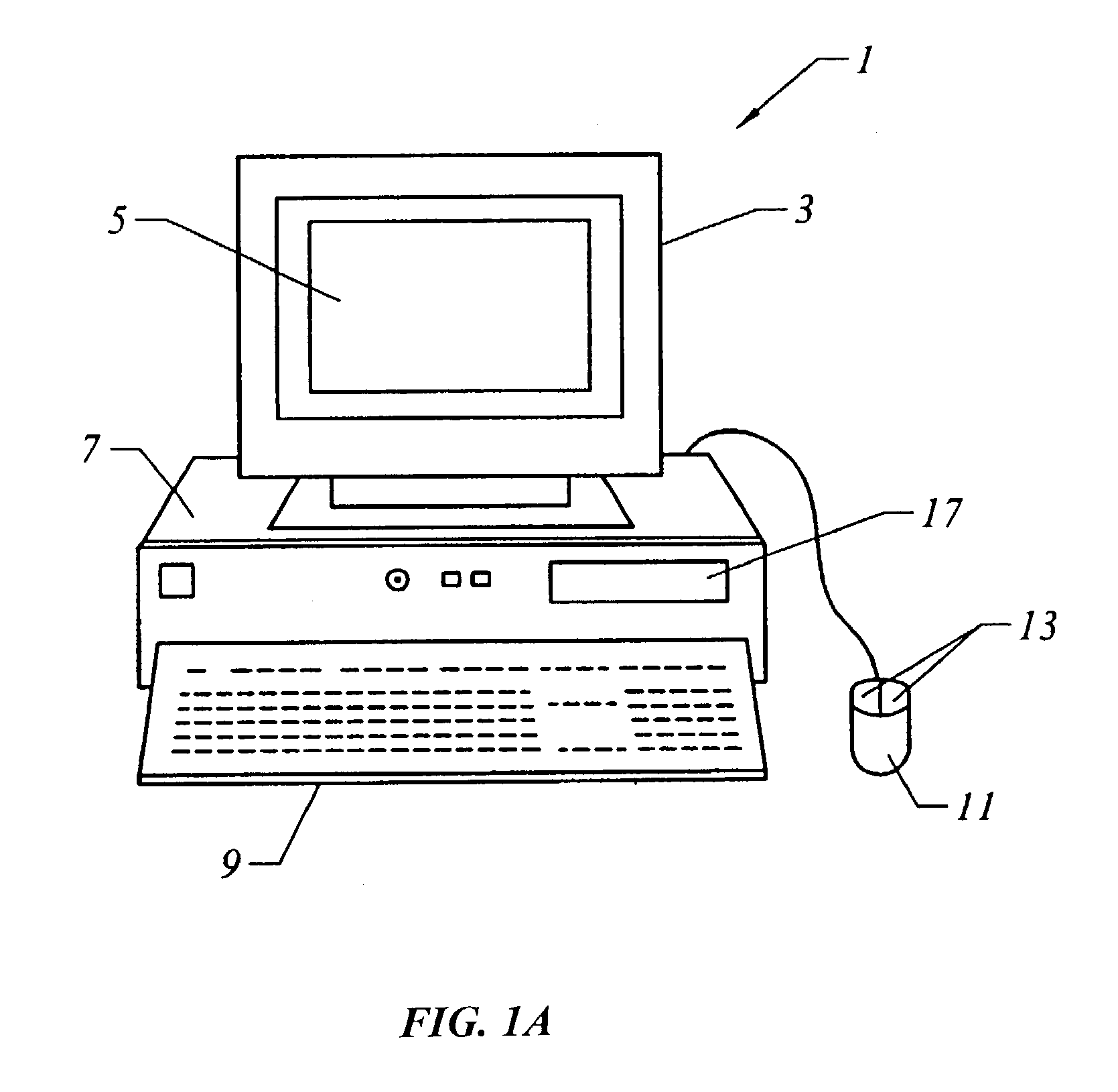
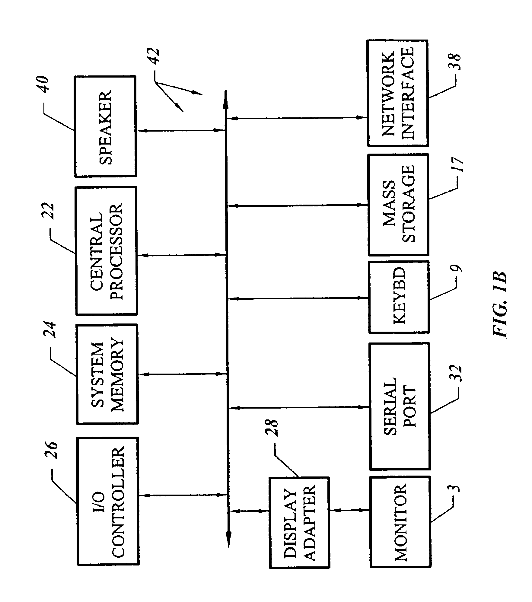
[0034]FIG. 1A shows a system of the present invention for performing physical resynthesis. In an embodiment, software of the invention executes on a computer workstation system, such as shown in FIG. 1A. FIG. 1A shows a computer system 1 that includes a monitor 3, screen 5, cabinet 7, keyboard 9, and mouse 11. Mouse 11 may have one or more buttons such as mouse buttons 13. Cabinet 07 houses familiar computer components, some of which are not shown, such as a processor, memory, mass storage devices 17, and the like. Mass storage devices 17 may include mass disk drives, floppy disks, Iomega ZIP™ disks, magnetic disks, fixed disks, hard disks, CD-ROMs, recordable CDs, DVDs, DVD-R, DVD-RW, Flash and other nonvolatile solid-state storage, tape storage, reader, and other similar media, and combinations of these. A binary, machine-executable version, of the software of the present invention may be stored or reside on mass storage devices 1...


PUM


Abstract

A multiple-pass synthesis technique improves the performance of a design. In a specific embodiment, synthesis is performed in two or more passes. In a first pass, a first synthesis is performed, and in a second or subsequent pass, a second synthesis or resynthesis is performed. During the first synthesis, the logic will be mapped to for example, the logic structures (e.g., logic elements, LUTs, synthesis gates) of the target technology such as a programmable logic device. Alternatively a netlist may be provided from a third party. Before the second synthesis, a fast or abbreviated fit may be performed of the netlist to a specific device (e.g., specific programmable logic device product). Before the second synthesis, the netlist obtained from the first synthesis (or provided by a third party) is unmapped and then the second synthesis is performed. Since a partial fit is performed, the second synthesis has more visibility and optimize the logic better than by using a single synthesis pass. After the second synthesis pass, a more detailed fit is performed.

Description

COPYRIGHT NOTICE[0001]A portion of the disclosure of this patent document contains material which is subject to copyright protection. The copyright owner has no objection to the facsimile reproduction by anyone of the patent document or the patent disclosure, as it appears in the U.S. Patent and Trademark Office patent file or records, but otherwise reserves all copyright rights whatsoever.BACKGROUND OF THE INVENTION[0002]The present invention relates to the area of electronic design automation of logic designs and in particular, to an aspect known as physical resynthesis of a logic design, especially using place and route timing delays to improve synthesis results.[0003]Integrated circuits are important building blocks of the modern age. Technology continues to evolve and integrated circuits continue to provide improved functionality. As integrated circuits improve, so do the electronics systems that are built using integrated circuits. There are many types of integrated circuits s...

Claims


Application Information

Patent Timeline
IPC IPC(8): G06F17/50G01R31/28G06F9/455
CPCG06F17/5068G06F30/39
Inventor HUTTON, MICHAEL D.PISTORIUS, JOACHIMVAN ANTWERPEN, BABETTEBAECKLER, GREGGYUAN, RICHARDHWANG, YEAN-YOW
Owner ALTERA CORP
Learn More