
Network management method

Inactive Publication Date: 2007-11-29
FUJITSU LTD
View PDF13 Cites 150 Cited by
  • Summary
  • Abstract
  • Description
  • Claims
  • Application Information

AI Technical Summary

Benefits of technology

[0011]It is an object of the present invention to provide the network managing method which the network manager can integrally grasp not only the physical and logical configurations of the system but the status of the spanning tree corresponding to the transmission paths.
[0014]Furthermore the present invention is to provide a method for monitoring by which an administrator of the system can monitor reliably the network whether the system is operating in intended status of spanning tree, such as a status of transmission paths, and of learning MAC addresses. Accordingly there is provided the method by which the administrator easily estimate whether the system is operating satisfactorily or not.
[0017]By virtue of function of the present invention described above, the network administrator can integrally grasp not only the intended the physical and logical configurations but the status of spanning tree which is non-visible transmission paths and the Mac address learning status.As a result, the function contribute to easily analyze and recover the network when the transmission path accidents and the abnormal status of MAC address learning, therefore the recovery time will be shorten.
[0019]According to the present invention, the status of spanning tree at every logical network configuration is displayed on a monitor, where the status of spanning tree is stored in a form linked with physical connection information and logical network information. The network administrator, therefore, can grasp integrally not only intended physical and logical configurations but the status of spanning tree (STP). The interruption in the network can be easily analyzed and the recovery time to proper service in the network will be shortened.
[0025]The present invention also improves the processing time for interruption analysis by the configuration for comparing the various kinds of information at a past time and other past time, or at a past time and the present time. For faster processing of interruption analysis, it is preferable to include configuration for detecting differences between the various kinds of information in two different times, where the past one of two different times is preferable to be a time closest to time before the interruption did not occur.
[0027]As an effect provided by the present invention, it is easily able to analyze the interrupt in the network because the abnormality is estimated from the relationship between the status of spanning tree information and the ports of the network device in which MAC address is learned, and the resultant abnormality is displayed. The abnormality is shown as example in FIG. 15, and a detail explanation will be described in later embodiment.

Problems solved by technology

The techniques disclosed in the references, however, are difficult to the status of real paths on the logical configuration of the network and a status of the learning of MAC addresses.
Therefore it will take a lot of time to find and analyze troubles on the network and recover the line, because the analysis on the troubles will be done manually to investigate the status of the real transmission paths or the learning of MAC addresses and will be estimated the probable trouble portion.
Furthermore, the network apparatus disclosed in the Reference 3(Japanese unexamined publication 2004-326790 could not detect an operating status of a network, where a connection between ports of devices is not connected by a cable defect or wrong wiring in practice in spite of the intention of a network manager that the connection is really connected and available on the design of the network.

Method used


Image

  • Network management method
  • Network management method
  • Network management method

Examples


Embodiment Construction

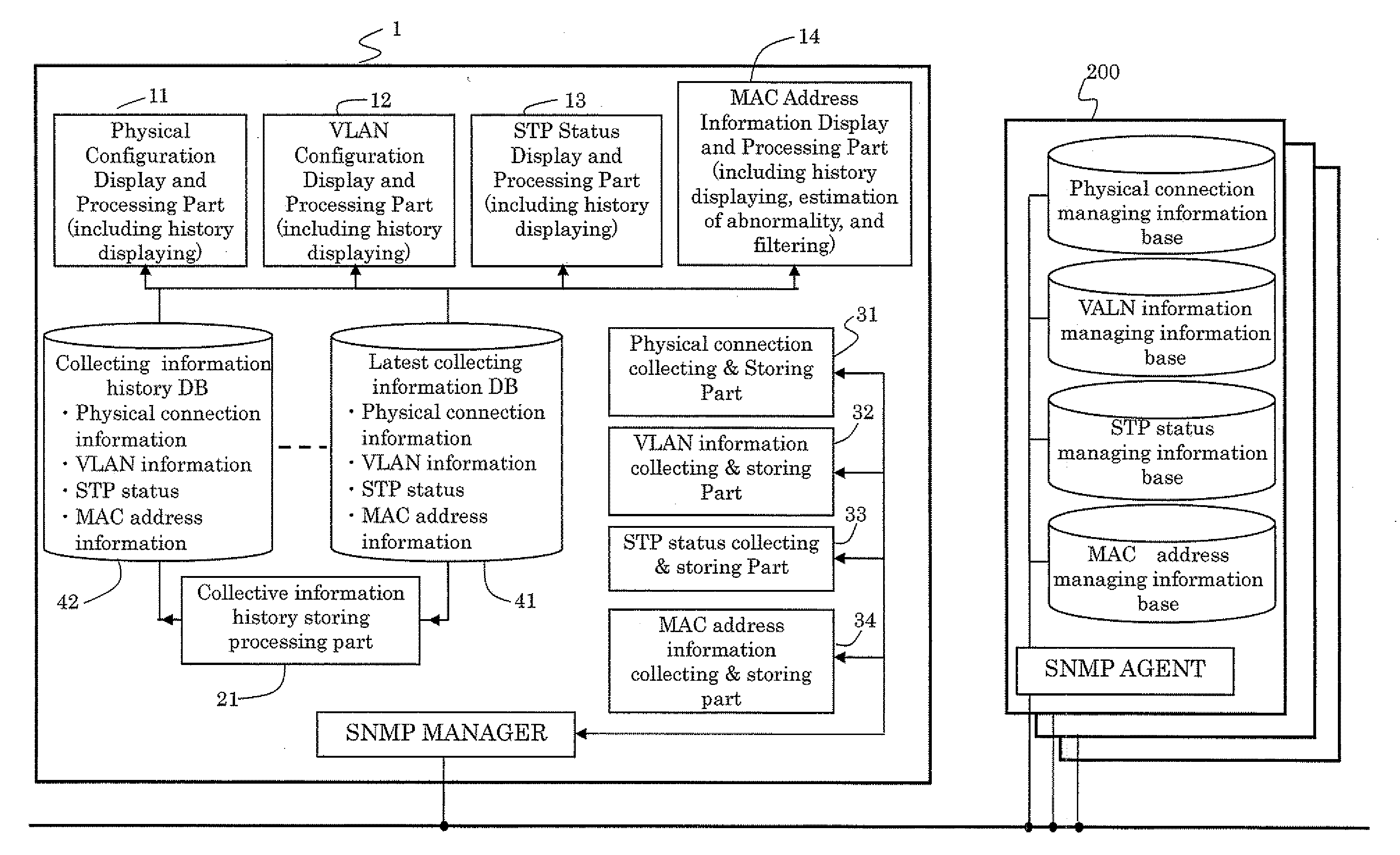
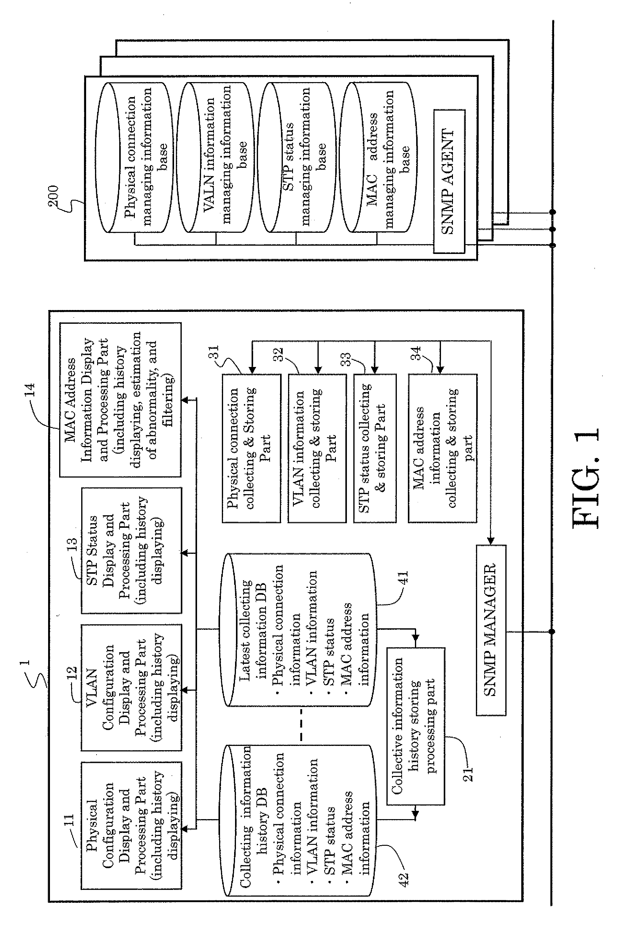
[0052]Referring to figures, the method for monitoring networks as an embodiment is explained. FIG. 1 shows a principal and schematic diagram of the embodiment.

[0053]On the network shown in FIG. 1, there are provided a monitoring terminal including a part of the present invention, a plurality of L3 and L2 switches as objects to be monitored.

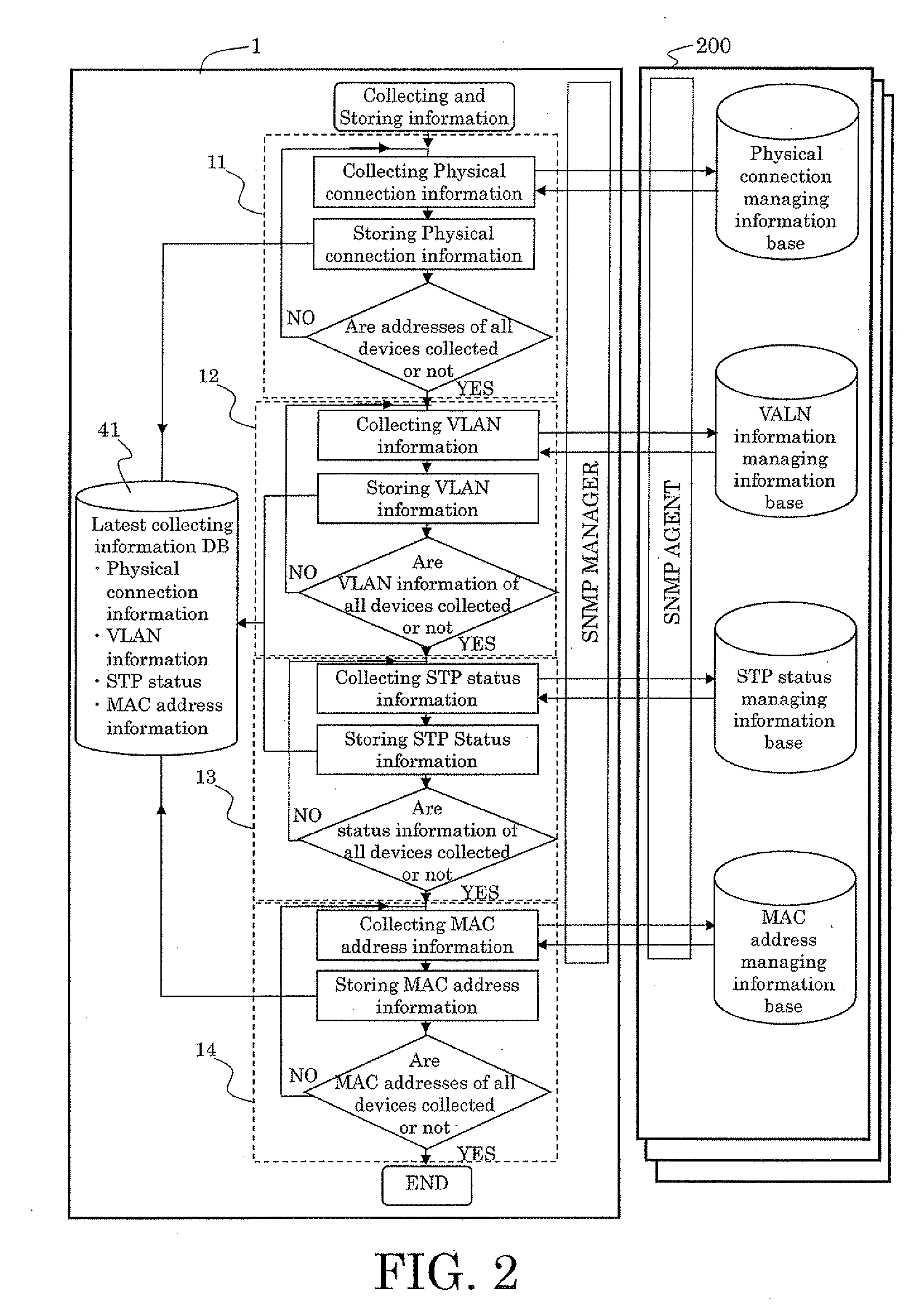
[0054]The monitoring terminal 1 shown in FIG. 1 includes a simple network management protocol (SNMP) manager which uses a standard protocol “SNMP” for collecting necessary information from each of devices 200 to be monitored. Furthermore, the monitoring equipment 1 includes processing part comprising; a physical connection information storing part 11 for collecting and storing physical connection information; a VLAN information storing part 12 for collecting and storing VLAN information; a spanning tree storing part 13 for collecting and storing status of spanning tree; a MAC address storing part 14 for collecting and storing MAC addresses; a hist...


PUM


Abstract

The present invention provides a method in which the physical connection information and the logical network configuration information are kinked to the status of spanning tree, and the status of spanning tree is displayed with the physical connection and the logical network configurations. The method can provide the better recognition about not only intended the physical and logical configurations but the status of spanning tree to a network administrator. Therefore, the network administrator can integrally recognize the status of the network and the failure in the network will be analyzed easily to recover the network to normal state in shorter time.

Description

BACKGROUND OF THE INVENTION[0001](1) Field of the Invention[0002]The present invention relates to a method for managing a network comprising a plurality of equipments, more specifically the method manages the network with use of information in addition of the information of physical connection among the equipments and the logical network construction information.[0003](2) Related Art[0004]A network managing method or system are disclosed in Japanese unexamined application 10-294731 and 11-340980, in which a physical configuration of the network and logical configuration such as Virtual LAN (VLAN) are displayed in corresponding with each other.[0005]In the systems as back ground, a control manager gathers information of network information, such as a method for identifying the physical connections, and corresponds to the information to logical network configurations including a Virtual LAN. The correspondence between both sets of information is displayed on a monitor, or the like.[00...

Claims


Application Information

Patent Timeline
IPC IPC(8): H04L12/28H04L12/70
CPCH04L41/0213H04L41/046H04L43/0817H04L41/0856H04L41/0853
Inventor KUBOTA, AKINORI
Owner FUJITSU LTD
Learn More