Stage device and exposure apparatus

a technology of exposure apparatus and stage device, which is applied in the direction of photomechanical apparatus, instruments, optics, etc., can solve the problems of entailment of tremendous technical difficulty, stage weight, and overall size of the stage, and achieve the effect of increasing the throughput of the exposure step and speed

Inactive Publication Date: 2005-05-24
NIKON CORP
View PDF20 Cites 688 Cited by
  • Summary
  • Abstract
  • Description
  • Claims
  • Application Information

AI Technical Summary

Benefits of technology

[0048]Next, the positioning method that makes use of the third stage device of the present invention comprises estimating the phase of the one measurement axis from the measured value of the other measurement axis in the estimation of the degree of interference of the one measurement axis from the measured value of the other measurement axis; comparing this estimated phase to the phase measured for the one measurement axis; and correcting the estimated value of the degree of interfer

Problems solved by technology

Consequently, a large movable mirror was needed if the movable range of the movable stage was to be expanded, and this inevitably led to the overall size of the stage being larger, which was a problem in that the stage was heavier and therefore more difficult to move quickly.
Also, machining a large movable mirror to the required degree of flatness entails tremendous technical difficulty, and fixing the movable mirror to the side of the movable stage without causing the mirror to bend also presents daunting technical difficulty.
Unfortunately, a decrease in the flatness of the movable mirror translates directly into a decrease in positioning precision of the stage by interferometer, so ultimately there is no choice but to limit the movable range of the movable stage.
In the former case, however, the use of a drive motor with a larger output increases the amount of heat generated from the drive motor.
This increase in the amount of heat causes subtle thermal deformation in the stage system, which could conceivably preclude obtaining the high positional precision required of the exposure appa

Method used


Image

  • Stage device and exposure apparatus
  • Stage device and exposure apparatus
  • Stage device and exposure apparatus

Examples


first embodiment

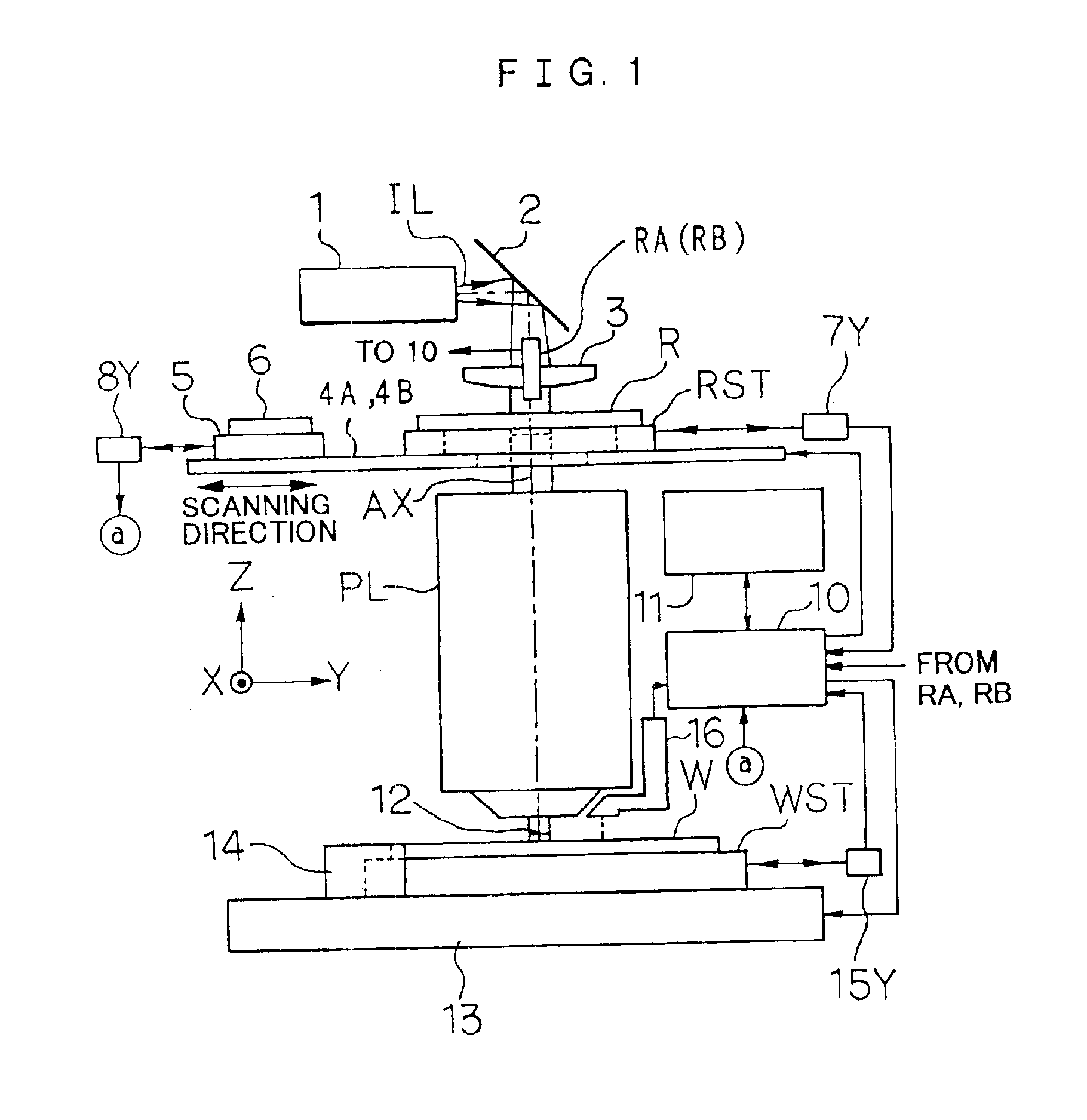
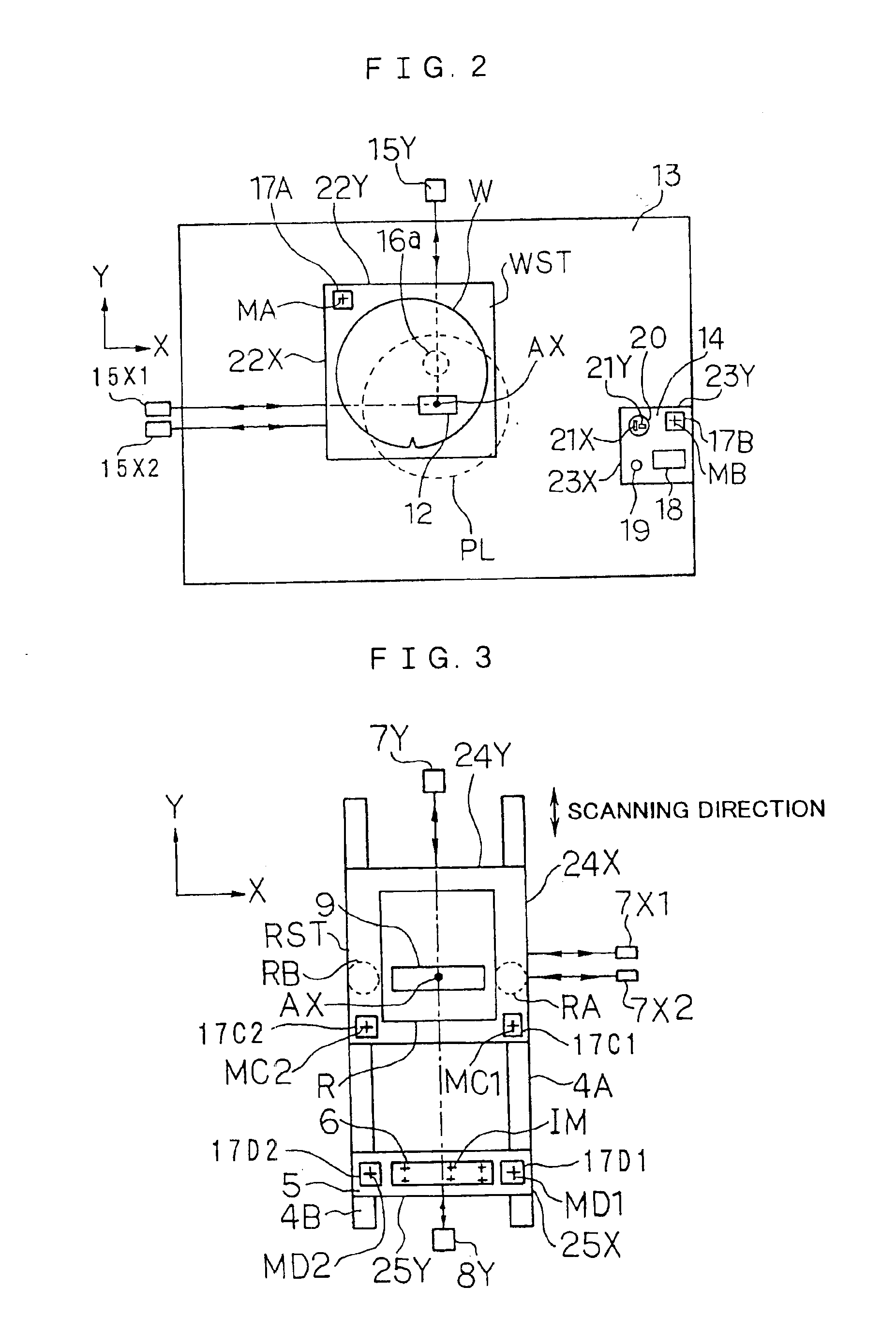
[0063]A preferred first embodiment of the present invention will now be described with reference to FIGS. 1 to 4. This is an example of applying the present invention to a step-and-scan type of projection exposure apparatus.

[0064]FIG. 1 illustrates the projection exposure apparatus in this example. In FIG. 1, exposure light IL is emitted during exposure by an illumination system 1 including an exposure light source, a beam shaping optical system, a fly-eye lens for making the illumination distribution uniform, a light quantity monitor, a variable aperture stop, a field stop, a relay lens system, and so forth. This light IL illuminates a slit-shaped illumination region of the pattern side (lower side) of a reticle R via a mirror 2 and a condenser lens 3. This exposure light IL can be excimer laser light such as KrF (248 nm wavelength) or ArF (193 nm wavelength), a higher harmonic wave from a YAG laser, an i-ray from a mercury vapor lamp (365 nm wavelength), or the like. The illuminat...

second embodiment

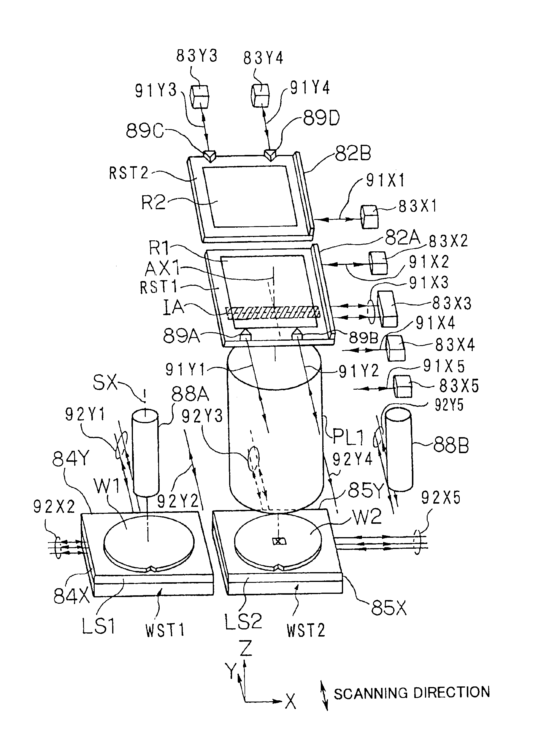
[0098]the present invention will now be described through reference to FIGS. 5 to 12. This is an example of applying the present invention to a step-and-scan type of projection exposure apparatus in which exposure is performed by the double exposure method.

[0099]FIG. 5 shows the simplified structure of the projection exposure apparatus in this example. In FIG. 5, the projection exposure apparatus of this example comprises a stage device equipped with wafer stages WST1 and WST2 as a plurality of movable stages for supporting and independently moving two-dimensionally wafers W1 and W2 as sensitive substrates on a base plate 86; a projection optical system PL1 disposed above this stage device; a reticle drive mechanism for driving in a specific scanning direction a reticle R1 or R2 (see FIG. 6) as a mask above the projection optical system PL1; an illumination system for illuminating the reticles R1 and R2 from above; and a control system for controlling these various components. In th...


PUM


Abstract

A stage device suitable for exposure apparatus used to produce semiconductor devices, is movable in an area wider than the measurement area of interferometer for position measurement, and is capable of measuring the position with high precision. When a movable stage moves from the position where the laser beams from laser interferometers are not applied into the measurement area of the laser interferometer, the position of reference mark is measured by a wafer alignment sensor, and the measurement value measured by the laser interferometer is corrected based on the results of the measurement by the wafer alignment sensor. When another movable stage enters the measurement area of the laser interferometer, the position of the reference mark is similarly measured by a wafer alignment sensor, and the measurement value measured by the laser interferometer is corrected based on the results of the measurement by the wafer alignment sensor.

Description

CROSS-REFERENCE[0001]This application is a Continuation Application of International Application No. PCT / JP98 / 05705 which was filed on Dec. 17, 1998 claiming the conventional priority of Japanese patent applications No. 9-364493 filed on Dec. 18, 1997 and No. 10-339789 filed on Nov. 30, 1998.BACKGROUND OF THE INVENTION[0002]1. Field of the invention[0003]This invention relates to a stage device for positioning a workpiece to be machined, for example, and to an exposure apparatus equipped with this stage device and used in transferring a mask pattern onto a substrate in a lithographic process for manufacturing semiconductor devices, liquid crystal display devices, thin film magnetic heads, and so forth. The present invention is particularly suitable for use in exposure apparatus having various mechanisms such as a mechanism for measuring imaging characteristics.[0004]2. Description of the Related Art[0005]High exposure precision is required of a batch exposure type (stepper type) or ...

Claims


Application Information

Patent Timeline
IPC IPC(8): G03F7/20H01L21/00H01L21/68
CPCG03F7/70716G03F7/70775G03F7/70741G03F7/70733
Inventor TANIGUCHI, TETSUOKAMIYA, SABURO
Owner NIKON CORP
Why Eureka
Try Eureka