Immersion device for an optical fiber for measuring the temperature of a melt

a technology of optical fiber and immersion device, which is applied in the direction of heat measurement, optical radiation measurement, instruments, etc., can solve the problems of scrap falling down, little room for installing an immersion device, and harsh conditions, and achieve the effect of simple and quick assembly and assembly

Inactive Publication Date: 2016-07-28
HERALUS ELECTRO NITE INT NV
View PDF6 Cites 2 Cited by
  • Summary
  • Abstract
  • Description
  • Claims
  • Application Information

AI Technical Summary

Benefits of technology

[0031]In a preferred embodiment, the stack is attached by gravity and / or due to a hook-like or U-shaped connection and / or due to form closure. This contributes to the possibility to assemble and to disassemble the immersion device in a simple and quick manner without the need for tools in places where space is limited.
[0032]In a preferred embodiment, at least the lower end wall of the stack, preferably both end walls of the stack, form an acute angle with the feeding channel so that the one, and more particularly both end walls, extend in a perpendicular direction or at least in an almost perpendicular direction in the working position. This avoids a jamming of guiding tube within the stack.

Problems solved by technology

In this environment, the conditions are harsh due to high temperatures.
Scrap may fall down and there is, as a rule, very little room to install an immersion device.

Method used


Image

  • Immersion device for an optical fiber for measuring the temperature of a melt
  • Immersion device for an optical fiber for measuring the temperature of a melt
  • Immersion device for an optical fiber for measuring the temperature of a melt

Examples


Embodiment Construction

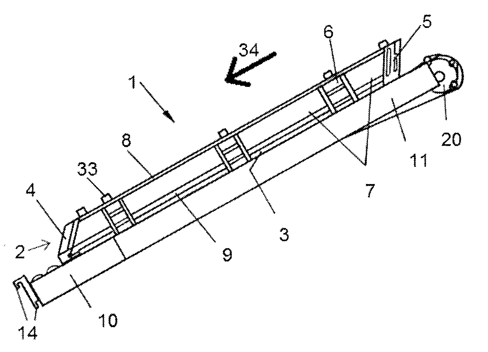
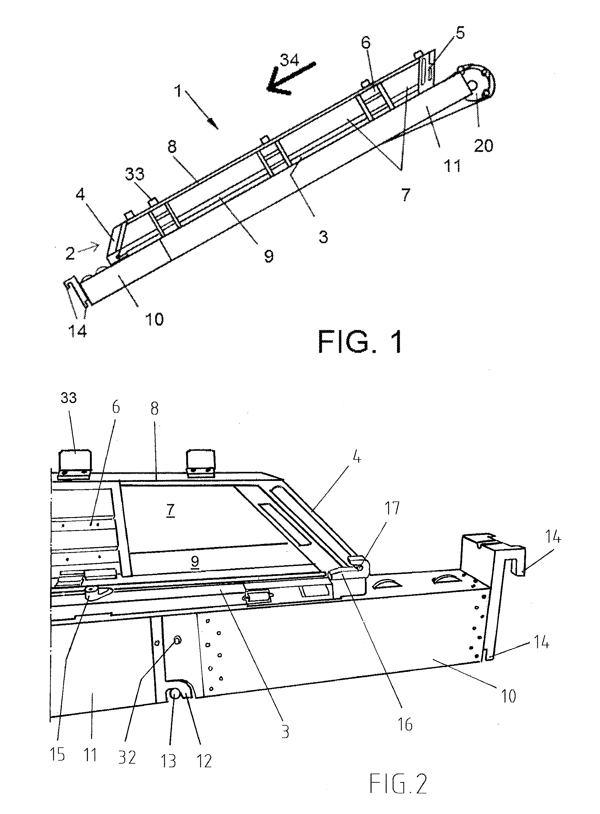
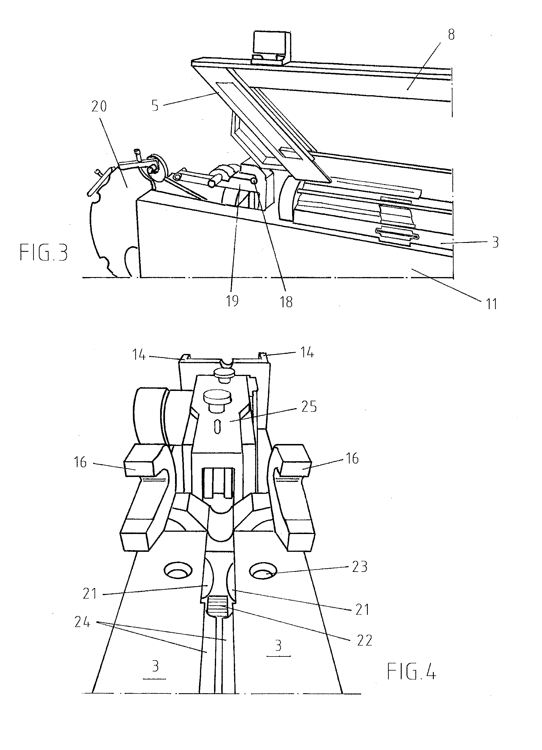
[0044]FIG. 1 shows an immersion device 1 for disposable guiding tubes of a robotic immersion device. The immersion device comprises a stack 2 for the disposable guiding tubes, as known from EP 2 799 824 A1. Two movable bars 3 define a feeding channel area for feeding an optical fiber into a disposable guiding tube and for feeding the disposable guiding tube together with the optical fiber into a melt. The bars 3 extend in a downhill direction in order facilitate the feeding of a guiding tube into a melt when the immersion device is connected to an access panel of a furnace, as known from EP 2 799 824 A1. The stack 2 is arranged above the bars 3 of the feeding channel so that a movable guiding tube can fall from the stack into the feeding channel.

[0045]The stack 2 comprises a lower end wall 4 and an upper end wall 5. Both end walls 4, 5 of the stack 2 form an acute angle with the bars 3 of the feeding channel, so that both end walls 4 and 5 extend in a perpendicular direction in the ...


PUM

PropertyMeasurementUnit
diameteraaaaaaaaaa
acute angleaaaaaaaaaa
temperatureaaaaaaaaaa

Abstract

An immersion device for disposable guiding tubes of a robotic immersion device includes a stack for the disposable guiding tubes, a feeding channel for feeding an optical fiber into the disposable guiding tube and for feeding the disposable guiding tube together with the optical fiber into a melt, and a transfer mechanism for transferring one disposable guiding tube from the stack into the channel.

Description

BACKGROUND OF THE INVENTION[0001]The present invention relates to an immersion device for measuring the temperature of a metal with an optical fiber in a metallurgical vessel.[0002]An immersion device for measuring the temperature of a metal with an optical fiber in a metallurgical vessel is known from EP 2 799 824 A1. More particularly, EP 2 799 824 A1 discloses a robotic immersion device for measuring the temperature in a metallurgical vessel using a molten metal-immersed consumable optical fiber and immersion equipment capable of inserting a temperature device through a side wall of an EAF to a predictable molten steel immersion depth with a temperature-to-temperature measuring frequency of less than 20 seconds. The robotic immersion device comprises a disposable guiding tube having an immersion end and a second end, opposite to the immersion end. An optical fiber can be partially arranged in the disposable guiding tube, whereby the inner diameter of the disposable guiding tube i...

Claims


Application Information

Patent Timeline
Patent Type & Authority Applications(United States)
IPC IPC(8): G01K1/14G01K11/32
CPCG01K11/32G01K1/146B22D2/006G01J5/004G01J5/0821G01J5/021G01J5/04G01J5/05B22D2/00G01K11/00G01K11/06
Inventor NEYENS, GUIDO JACOBUSTHYS, MICHELSTEVENS, FRANK
Owner HERALUS ELECTRO NITE INT NV
Why Eureka
Try Eureka