
Wind tunnel convergent type power generator
A technology of generators and wind tunnels, which is applied to wind turbine components, wind engines, wind engine control, etc., and can solve problems such as the inability of the empennage 13 to control the steering of the wind turbine 1, the inability to use the wind and the empennage, and increase the area.
Patent Information
- Authority / Receiving Office
- CN · China
- Patent Type
- Applications(China)
- Current Assignee / Owner
- Publication Date
- 2007-08-01
- Estimated Expiration
- Not applicable · inactive patent
Smart Images
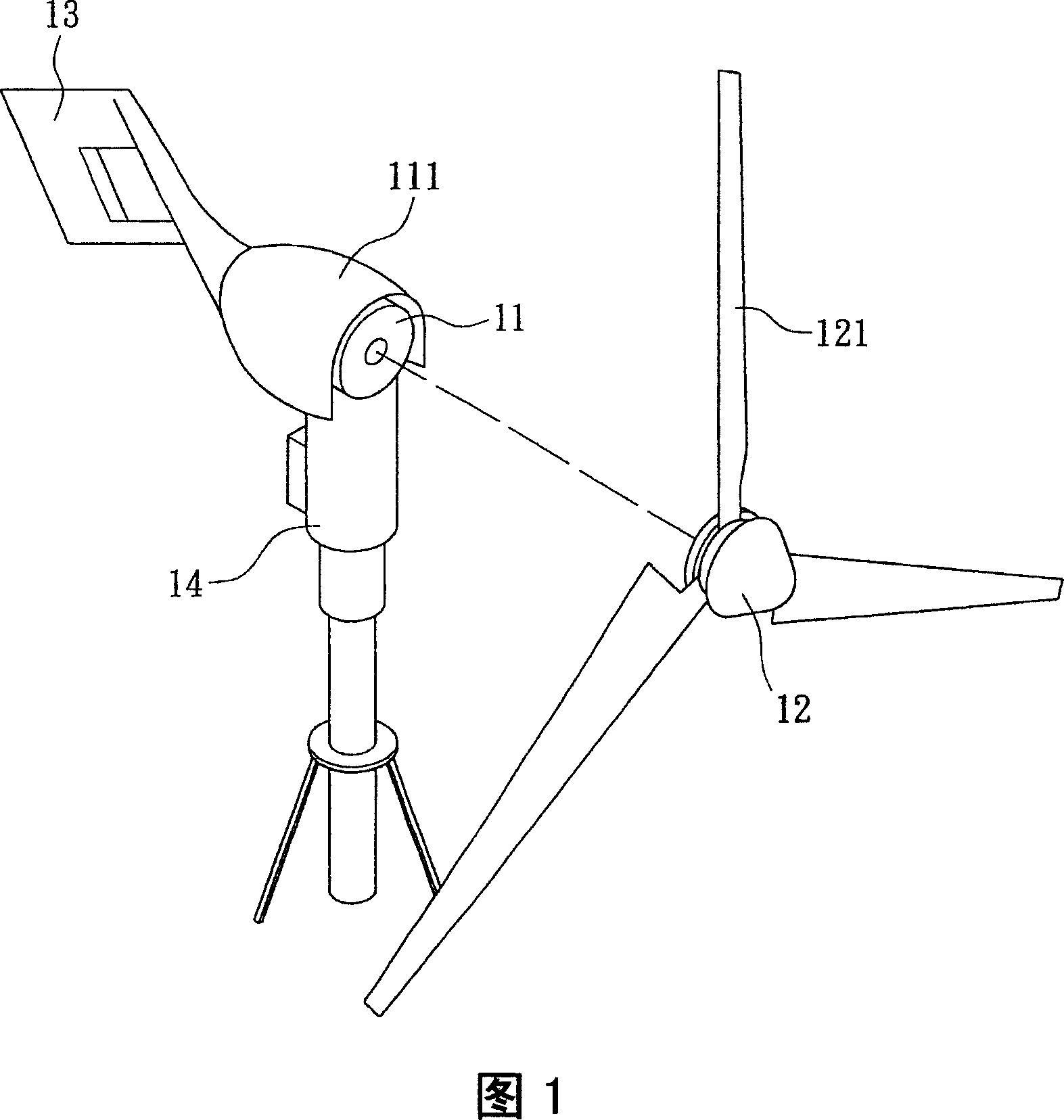
Figure 1 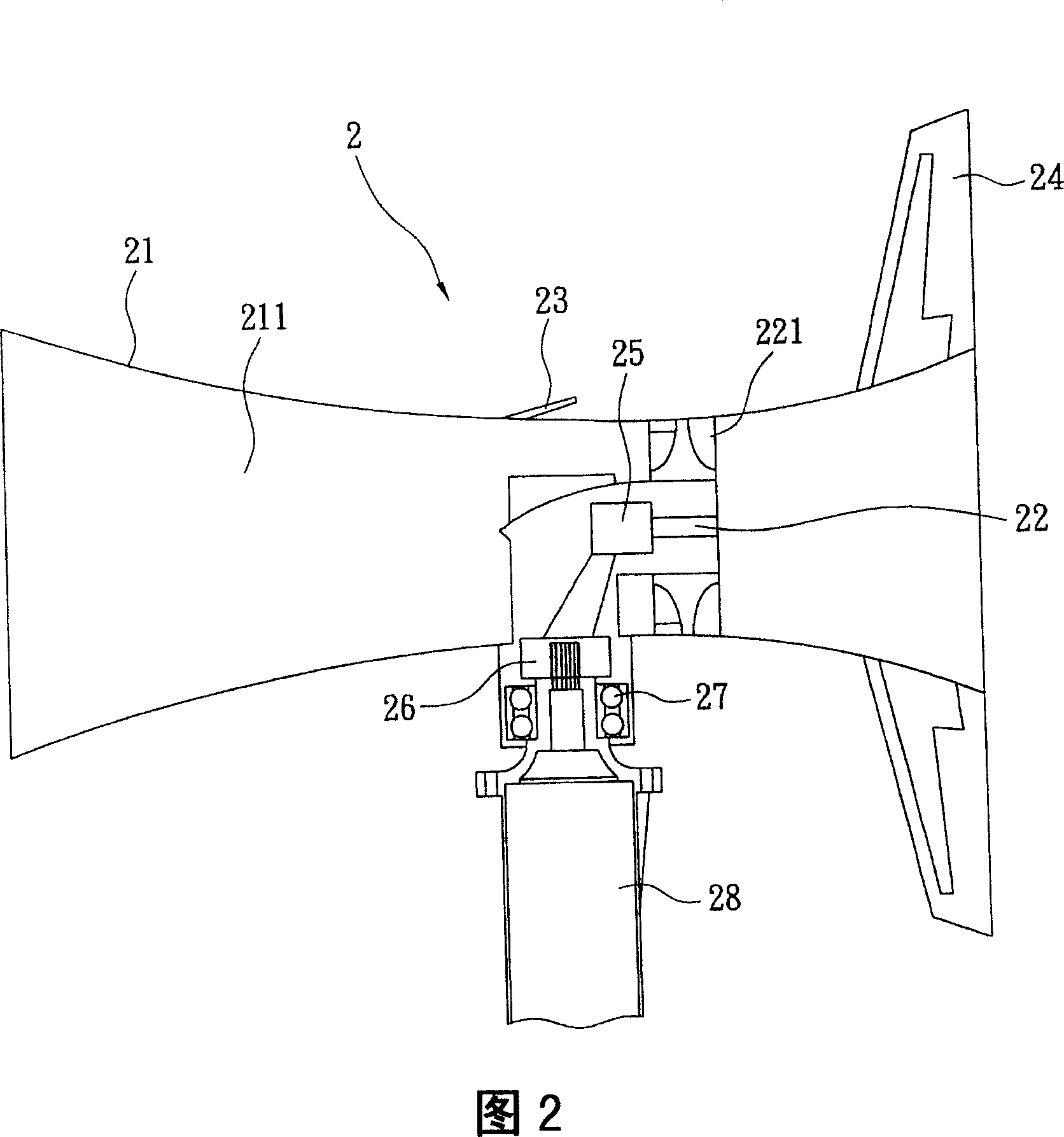
Figure 2
Abstract
Description
technical field
[0001] The invention relates to a wind tunnel convergence type power generator, in particular to a wind tunnel convergence type power generator with small volume and high efficiency. Background technique
[0002] As the world's oil production decreases and the greenhouse effect becomes more and more serious, countries around the world are committed to developing non-polluting energy, so wind power and solar power have become popular targets.
[0003] Known wind power generator 1 (as Fig. 1), it comprises generator body 11, windmill 12, empennage 13 and fixed frame 14; Fixed frame 14 connects generator body 11 with a bearing (figure omitted), and generator body 11 The windmill 12 is connected with another bearing, and a plurality of blades 121 are arranged on the windmill 12, and the blades 121 and the axis line of the rotating shaft connected to the windmill 12 all have a fixed acute angle, and the empennage 13 is arranged on the shell of the generator body 1...
Examples
Embodiment Construction
[0021] Referring to Fig. 2, the present invention provides a wind tunnel convergence type power generator 2, which includes an outer cover 21, a turbine rotor 22, a discharge valve 23 and an empennage 24; the outer cover 21 is a circular tube and presents a tapered and then gradually expanded appearance , and a single or combined outer cover made by metal or composite material molding such as casting, and the turbine rotor 22 is arranged in the inner flow channel 211 formed by the outer cover 21, and is located between the taper and the outer cover 21. In the gradually expanding throat portion, the axis line of the turbine rotor 22 coincides with the axis line of the casing 21 . In addition, the air release valve 23 is arranged adjacent to the turbine rotor 22 and is located on the wall of the housing 21 in the air inlet direction; as for the empennage 24, it is arranged on the surface of the housing 21 positioned at the air outlet end in a direction perpendicular to the axis l...