
Display device, electronic device, and display device control method
一种显示装置、控制方法的技术,应用在静态指示器、仪器等方向,能够解决刷新率下降等问题,达到降低功耗、维持显示质量、抑制功耗的效果
Patent Information
- Authority / Receiving Office
- CN · China
- Patent Type
- Applications(China)
- Current Assignee / Owner
- Publication Date
- 2016-06-08
Smart Images
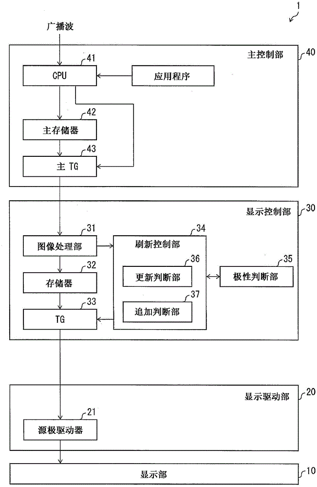
Figure 1 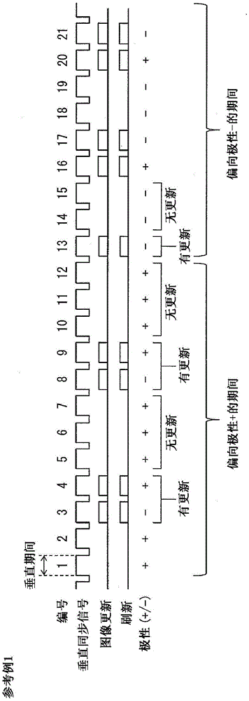
Figure 2 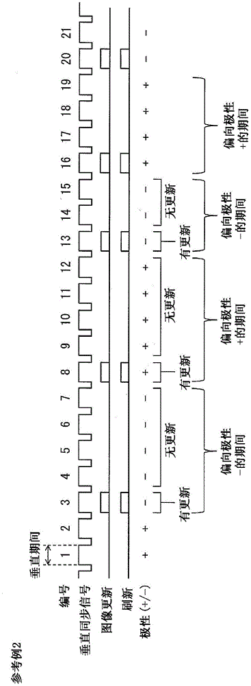
Figure 3
Abstract
Description
technical field
[0001] The present invention relates to a display device, an electronic device and a control method of the display device. Background technique
[0002] In recent years, thin, lightweight, and low power consumption display devices typified by liquid crystal display devices have remarkably spread. Typical mounting forms of such a display device are, for example, a mobile phone, a smart phone, a notebook PC (Personal Computer: personal computer), and the like. In addition, it is expected that the development and popularization of electronic paper, which is a thinner display device, will also advance rapidly in the future. Under such circumstances, reducing power consumption has become a common problem in various display devices.
[0003] In conventional CG (Continuous Grain: continuous grain) silicon TFT liquid crystal display panels, amorphous silicon TFT liquid crystal display panels, etc., it is necessary to refresh the screen at 60 Hz. Therefore, in orde...
Examples
Embodiment approach 1
[0033] (Configuration of Display Device 1 )
[0034] figure 1 It is a block diagram showing the configuration of the display device 1 of the present embodiment. The display device 1 includes a display unit 10 , a display drive unit 20 , a display control unit 30 , and a main control unit 40 . The display device 1 is a liquid crystal display device. In addition, the present invention is not limited to liquid crystal display devices, and can be applied to display devices that perform polarity inversion.
[0035] The display drive unit 20 is a COG driver mounted on a glass substrate of the display unit 10 in a COG (Chipon Glass: chip on glass) format, and drives the display unit 10 . The main control unit 40 is a control board including a control circuit formed on the board, and is mainly responsible for the control of the main side of the display device 1 (for the control of electronic equipment). The display control unit 30 is a control board provided independently of the ...
reference example 1
[0060] figure 2 It is a timing chart of image update and refresh of Reference Example 1 for comparison. exist figure 2 , the horizontal axis is time. exist figure 2 In , the vertical synchronization signal is a signal defining each vertical period, and here, for convenience, each vertical period is numbered. exist figure 2 In , the rectangle of "image update" or "refresh" indicates that there is image update or refresh in the vertical period, and "polarity" indicates the polarity of the pixel in the vertical period (the polarity of the data signal written to the pixel) .
[0061] In the display device of Reference Example 1, refreshing (writing data signals to pixels) is performed only in the vertical period in which the image is updated, and no refreshing is performed in the vertical period in which the image is not updated. Accordingly, power consumption during a period when no image update is performed can be reduced. In addition, in Reference Example 1, the pola...
reference example 2
[0066] image 3 It is a timing chart of image update and refresh of Reference Example 2 for comparison. image 3 Each element in represents and figure 2 same meaning. image 3 shown in Reference Example 2 with figure 2 The reference example 1 shown differs in the timing of image update.
[0067] For example, when the image is updated as in Reference Example 2, the polarity is also reversed at the timing of the image update, so the period during which one polarity is biased is shorter than that of Reference Example 1. Therefore, in the case of Reference Example 2, the flicker is not easily seen by the user.
[0068] (Operation example 1)
[0069] In this embodiment, in order to solve the above-mentioned problem that the flicker is seen, an additional refresh is performed during the period when the image is not updated. The operation of the display device 1 of this embodiment will be described below.
[0070] Figure 4 It is a sequence diagram showing image update and ...