
Laser large working distance auto-collimation device and method
A working distance and self-collimation technology, which is applied in precision measurement and optical engineering fields, can solve the problems that self-collimation and micro-angle measurement cannot be realized, the range should not be too large, and the reflected beam deviates from the entrance pupil, etc., so as to increase self-collimation The working range, simple structure of the device, and the effect of fast and real-time return compensation
Patent Information
- Authority / Receiving Office
- CN · China
- Patent Type
- Applications(China)
- Current Assignee / Owner
- Publication Date
- 2017-01-11
Smart Images
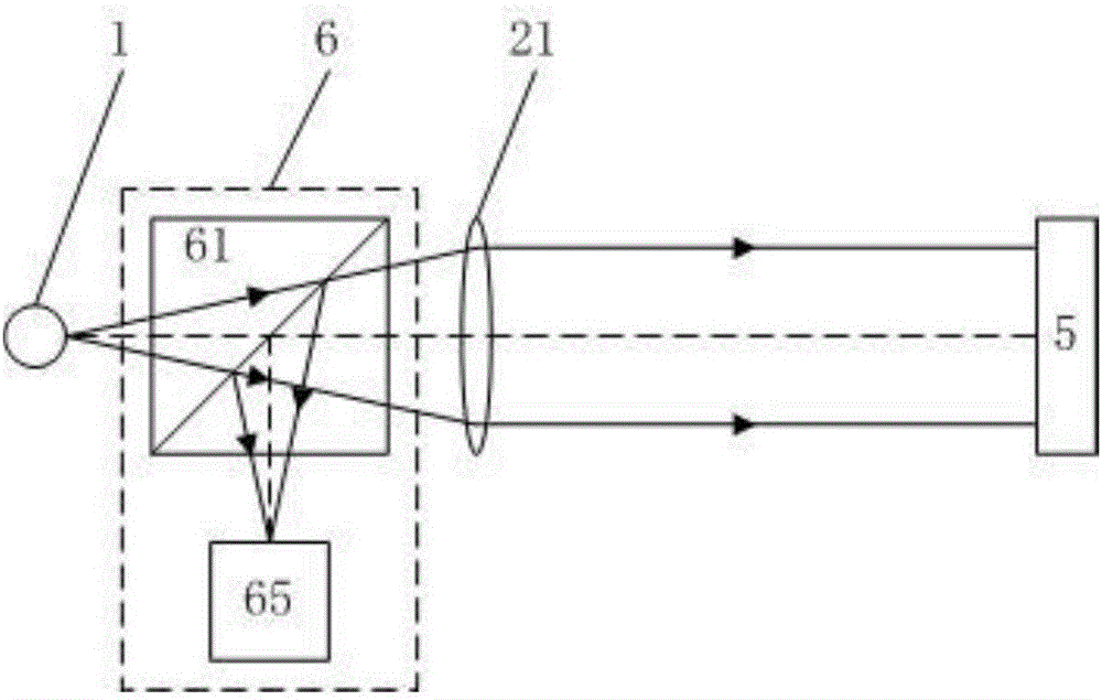
Figure 1 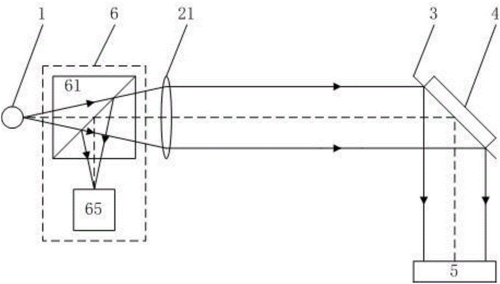
Figure 2 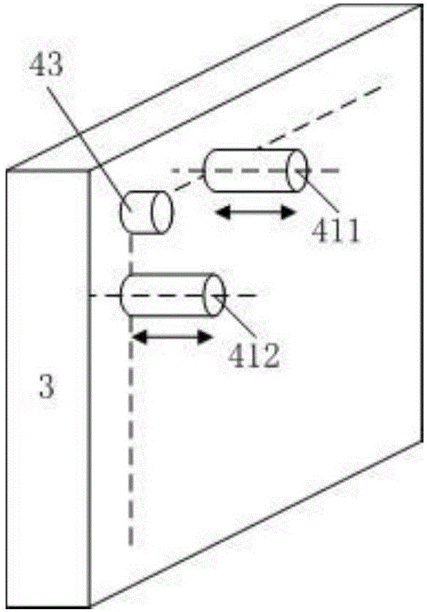
Figure 3
Abstract
Description
technical field
[0001] The invention belongs to the technical field of precision measurement and the field of optical engineering, and in particular relates to a laser large working distance self-collimation device and method. Background technique
[0002] In the fields of precision measurement technology, optical engineering, cutting-edge scientific experiments and high-end precision equipment manufacturing, there is an urgent need for large working range and high-precision laser self-collimation technology at a large working distance. It supports the development of technology and equipment in the above fields.
[0003] In the field of precision measurement technology and instruments, the combination of laser autocollimator and circular grating can measure any line angle; the combination of laser autocollimation technology and polyhedral prism can measure surface angle and circular indexing; the maximum working distance From a few meters to hundreds of meters; resolution f...
Examples
specific Embodiment 1
[0077] This embodiment is an embodiment of a laser autocollimation device with a large working distance.
[0078] The laser large working distance self-collimation device of this embodiment, the structural diagram is as follows figure 2 shown. The self-collimation device includes a light source 1, a transmissive collimator mirror 21, a reflector 3, and a feedback imaging system 6. The reflector 3 is provided with an angle adjustment measuring device 4; After the straight mirror 21 is collimated into a parallel light beam, it is reflected by the reflector 3 and incident on the surface of the measured object 5; the light beam reflected from the surface of the measured object 5 is then reflected by the reflective mirror 3 and collected by the feedback imaging system 6 imaging;
[0079] The feedback imaging system 6 is arranged between the light source 1 and the transmissive collimator 21, including a first feedback beamsplitter 61 and an image sensor 65 arranged at the focal p...
specific Embodiment 2
[0083] This embodiment is an embodiment of a laser autocollimation device with a large working distance.
[0084] The laser large working distance self-collimation device of this embodiment, the structural diagram is as follows Figure 7 shown. On the basis of the specific embodiment 1, the laser large working distance autocollimation device of this embodiment is also provided with a wavefront detection system 7 and a wavefront compensation system 8;
[0085] The wavefront detection system 7 includes a wavefront detection spectroscope 71 and an air disturbance wavefront detector 72; the wavefront detection spectroscope 71 is arranged between the reflector 3 and the measured object 5, and the air disturbance wavefront detector 72 is arranged on the reflected optical path of the wavefront detection spectroscope 71, and the mirror deformation wavefront detector 73 is arranged on the secondary reflected optical path of the reflector 3;
[0086] The wavefront compensation system ...
specific Embodiment 3
[0088] This embodiment is an embodiment of a laser autocollimation device with a large working distance.
[0089] The laser large working distance self-collimation device of this embodiment, the structural diagram is as follows Figure 8 shown. On the basis of the specific embodiment 1, the laser large working distance autocollimation device of this embodiment is also provided with a wavefront detection system 7 and a wavefront compensation system 8;
[0090] The wavefront detection system 7 includes a wavefront detection beamsplitter 71 and a mirror deformation wavefront detector 73; the wavefront detection beamsplitter 71 is arranged between the mirror 3 and the measured object 5, and the air disturbance wavefront detection The device 72 is arranged on the reflected optical path of the wavefront detection spectroscope 71, and the mirror deformation wavefront detector 73 is arranged on the secondary reflected optical path of the reflector 3;
[0091] The wavefront compensat...